Dell Dimension 4590T Service Manual
Dell Dimension 4590T Manual
 |
View all Dell Dimension 4590T manuals
Add to My Manuals
Save this manual to your list of manuals |
Dell Dimension 4590T manual content summary:
- Dell Dimension 4590T | Service Manual - Page 1
Service Manual Before indicates potential damage to hardware or loss of data if instructions are not followed. WARNING: A WARNING indicates a potential for registered trademark owned by Bluetooth SIG, Inc. and is used by Dell under license. Other trademarks and trade names may be used in this - Dell Dimension 4590T | Service Manual - Page 2
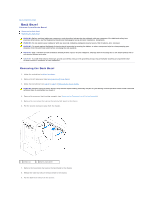
Bezel Alienware Aurora Service Manual Removing the Back service technician should perform repairs on your computer. Damage due to servicing that is not authorized by Dell is side-panel (see Removing the Left Side-Panel). 3. Follow the instructions from step 3 to step 7 in Removing the Power Supply. - Dell Dimension 4590T | Service Manual - Page 3
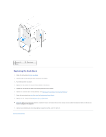
the security lock panel to the chassis. 6. Replace the processor liquid-cooling assembly (see Replacing the Processor Liquid-Cooling Assembly). 7. Follow the instructions from step 4 to step 8 in Replacing the Power Supply. 8. Replace the left side-panel (see Replacing the Left Side-Panel). CAUTION - Dell Dimension 4590T | Service Manual - Page 4
Begin Alienware Aurora Service Manual Recommended Tools Turning Off Your Computer Safety Instructions This manual provides procedures for screwdriver l Hex nut driver l BIOS executable update program available at support.dell.com Turning Off Your Computer CAUTION: To avoid losing data, save and - Dell Dimension 4590T | Service Manual - Page 5
CAUTION: To disconnect a network cable, first unplug the cable from your computer and then unplug the cable from the network device. 3. Disconnect all telephone or network cables from the computer. 4. Disconnect your computer and all attached devices from their electrical outlets. 5. Disconnect all - Dell Dimension 4590T | Service Manual - Page 6
Aurora Service Manual The BIOS may require flashing when an update is available or when replacing the system board. To flash the BIOS: 1. Turn on the computer. 2. Go to support.dell.com/support/downloads the file icon on the desktop and follow the instructions on the screen. Back to Contents Page - Dell Dimension 4590T | Service Manual - Page 7
Alienware Aurora Service Manual Removing the service technician should perform repairs on your computer. Damage due to servicing that is not authorized by Dell purchasing your computer. Removing the WiFi/Bluetooth Card 1. Follow the instructions in Before You Begin. 2. Remove the left side-panel - Dell Dimension 4590T | Service Manual - Page 8
1 thumbscrew 2 WiFi/Bluetooth assembly Replacing the WiFi/Bluetooth Card 1. Follow the instructions in Before You Begin. 2. Align the tab on the WiFi/Bluetooth assembly with the slot on the chassis. 3. Tighten the thumbscrew that secures the WiFi/ - Dell Dimension 4590T | Service Manual - Page 9
to Contents Page Coin-Cell Battery Alienware Aurora Service Manual Removing the Coin-Cell Battery Replacing the Coin-Cell manufacturer's instructions. CAUTION: Only a certified service technician should perform repairs on your computer. Damage due to servicing that is not authorized by Dell is not - Dell Dimension 4590T | Service Manual - Page 10
3. Replace the PCI-Express card(s) (see Replacing the PCI-Express Card(s)). 4. Close the PCI shroud (see Closing the PCI Shroud). 5. Replace the left side-panel (see Replacing the Left Side-Panel). CAUTION: Before turning on the computer, replace all screws and ensure that no stray screws remain - Dell Dimension 4590T | Service Manual - Page 11
Aurora Service Manual Removing service technician should perform repairs on your computer. Damage due to servicing that is not authorized by Dell memory fan 3 memory fan cable 2 tab Replacing the Memory Fan 1. Follow the instructions in Before You Begin. 2. Align the tabs on the memory fan with the - Dell Dimension 4590T | Service Manual - Page 12
-drive fan assembly out of the chassis. 1 hard-drive fan assembly cable 2 hard-drive fan assembly Replacing the Hard-Drive Fan Assembly 1. Follow the instructions in Before You Begin. 2. Push the hard-drive fan assembly into the hard-drive fan assembly bay. 3. Route the cable through the slot in the - Dell Dimension 4590T | Service Manual - Page 13
out of the metal brackets on the chassis. 1 tabs (2) 2 PCI-fan assembly 3 PCI-fan assembly cable Replacing the PCI-Fan Assembly 1. Follow the instructions in Before You Begin. 2. Align the PCI-fan assembly with the metal brackets on the chassis. 3. Slide the PCI-fan assembly into the chassis - Dell Dimension 4590T | Service Manual - Page 14
Back to Contents Page Front Bezel Alienware Aurora Service Manual Removing the Front Bezel Replacing the Front Bezel WARNING (s). CAUTION: Only a certified service technician should perform repairs on your computer. Damage due to servicing that is not authorized by Dell is not covered by your - Dell Dimension 4590T | Service Manual - Page 15
1 front bezel 2 screws (3) Replacing the Front Bezel 1. Follow the instructions in Before You Begin. 2. Align the front bezel with the front of the chassis. 3. Replace the three screws on the right side that secure the - Dell Dimension 4590T | Service Manual - Page 16
provide support for hard drives from sources other than Dell or Alienware. NOTE: If you are installing a hard drive from a source other than Dell or Alienware, you need to install an operating system, drivers, and utilities on the new hard drive. Removing the Hard Drive(s) 1. Follow the instructions - Dell Dimension 4590T | Service Manual - Page 17
hard-drive bracket and lift the hard drive out of the bracket (if applicable). 1 hard drive 2 tabs (4) Replacing the Hard Drive(s) 1. Follow the instructions in Before You Begin. NOTE: See the documentation that shipped with your new hard drive and ensure that the jumper positioning is correct - Dell Dimension 4590T | Service Manual - Page 18
it snaps into place. 8. Connect your computer and devices to electrical outlets and then turn them on. Removing the Media Card Reader 1. Follow the instructions in Before You Begin. 2. Press the AlienHead on the front of your computer to lower the drive panel. 3. Remove the left side-panel (see - Dell Dimension 4590T | Service Manual - Page 19
the Media Card Reader out of the FlexBay dock. 1 Media Card Reader 3 FlexBay dock 2 screws (4) Replacing the Media Card Reader 1. Follow the instructions in Before You Begin. 2. Remove the new Media Card Reader from its packaging. Save the original packaging for storing or shipping the Media Card - Dell Dimension 4590T | Service Manual - Page 20
Alienware Aurora Service Manual Removing the service technician should perform repairs on your computer. Damage due to servicing that is not authorized by Dell chassis. 1 screws (4) Replacing the Master I/O Board 1. Follow the instructions in Before You Begin. 2. Place the master I/O board in the - Dell Dimension 4590T | Service Manual - Page 21
4. Route and connect the cables that you removed from the connectors on the master I/O board. NOTE: For information on master I/O board connectors, see Master I/O Board Components. 5. Replace the PCI-fan assembly (see Replacing the PCI-Fan Assembly). 6. Replace the drive-bay shroud (see Replacing - Dell Dimension 4590T | Service Manual - Page 22
Back to Contents Page Left Side-Panel Alienware Aurora Service Manual Removing the Left Side-Panel Replacing the Left Side- (s). CAUTION: Only a certified service technician should perform repairs on your computer. Damage due to servicing that is not authorized by Dell is not covered by your warranty - Dell Dimension 4590T | Service Manual - Page 23
Replacing the Left Side-Panel 1. Follow the instructions in Before You Begin. 2. Align the tabs on the left side-panel with the slots on the side of the computer and push the panel - Dell Dimension 4590T | Service Manual - Page 24
.dell.com/manuals for information on the type of memory supported by your computer. Install only memory modules that are supported by your computer. NOTE: Memory modules purchased from Dell or Alienware are covered under your computer warranty. Removing Memory Module(s) 1. Follow the instructions - Dell Dimension 4590T | Service Manual - Page 25
1. Follow the instructions in Before You Begin. Recommended memory configuration: Type 1333 MHz,1600 MHz, and 1866 MHz DDR3 Slots Slots 1 and 2 or slots 1 - 4 2. Align the notch on - Dell Dimension 4590T | Service Manual - Page 26
Check the amount of memory (RAM) listed. Back to Contents Page - Dell Dimension 4590T | Service Manual - Page 27
Back to Contents Page PCI-Express Card(s) Alienware Aurora Service Manual Removing the PCI-Express Card(s) Replacing the PCI-Express CAUTION: Only a certified service technician should perform repairs on your computer. Damage due to servicing that is not authorized by Dell is not covered by your - Dell Dimension 4590T | Service Manual - Page 28
Replacing the PCI-Express Card(s) 1. Follow the instructions in Before You Begin. 2. Remove the screw that secures the filler bracket and remove the filler bracket to create a card-slot opening (if applicable). 1 filler - Dell Dimension 4590T | Service Manual - Page 29
- Dell Dimension 4590T | Service Manual - Page 30
Contents Page Processor Liquid-Cooling Assembly Alienware Aurora Service Manual Removing the Processor Liquid-Cooling Assembly Replacing the CAUTION: Only a certified service technician should perform repairs on your computer. Damage due to servicing that is not authorized by Dell is not covered by - Dell Dimension 4590T | Service Manual - Page 31
1. Follow the instructions in Before You Begin. 2. Align the screw holes on the processor liquid-cooling assembly with the screw holes on the chassis rear wall. 3. Replace the - Dell Dimension 4590T | Service Manual - Page 32
Processor Alienware Aurora Service Manual Removing the Processor Replacing the Processor WARNING: Before working inside your computer, read the safety information that shipped with your computer. For additional safety best practices information, see the Regulatory Compliance Homepage at www.dell.com - Dell Dimension 4590T | Service Manual - Page 33
to fall on the pins in the socket. CAUTION: Ground yourself by touching an unpainted metal surface on the back of the computer. 1. Follow the instructions in Before You Begin. 2. Unpack the new processor. Ensure that you do not to touch the underside of the processor. CAUTION: You must position the - Dell Dimension 4590T | Service Manual - Page 34
CAUTION: Ensure that you apply new thermal grease. New thermal grease is critical for ensuring adequate thermal bonding, which is a requirement for optimal processor operation. 9. Apply the new thermal grease to the top of the processor. 10. Replace the processor liquid-cooling assembly (see - Dell Dimension 4590T | Service Manual - Page 35
Back to Contents Page Power Supply Alienware Aurora Service Manual Removing the Power Supply Replacing the Power Supply WARNING (s). CAUTION: Only a certified service technician should perform repairs on your computer. Damage due to servicing that is not authorized by Dell is not covered by your - Dell Dimension 4590T | Service Manual - Page 36
the power supply to the bezel. 9. Remove the bezel from the power supply. 1 bezel 2 screws (4) 3 power supply Replacing the Power Supply 1. Follow the instructions in Before You Begin. 2. Align the screw holes on the power supply with the screw holes on the bezel. 3. Replace the four screws that - Dell Dimension 4590T | Service Manual - Page 37
to Contents Page Right Side-Panel(s) Alienware Aurora Service Manual Removing the Right-Side Top Panel Replacing the Right (s). CAUTION: Only a certified service technician should perform repairs on your computer. Damage due to servicing that is not authorized by Dell is not covered by your warranty - Dell Dimension 4590T | Service Manual - Page 38
to the computer. 8. Connect your computer and all attached devices to electrical outlets, and turn them on. Removing the Lighting Board 1. Follow the instructions in Before You Begin. 2. Remove the right-side top panel (see Removing the Right-Side Top Panel). 3. Disconnect the lighting-board cable - Dell Dimension 4590T | Service Manual - Page 39
the computer. 7. Connect your computer and all attached devices to electrical outlets, and turn them on. Removing the Right-Side Middle Panel 1. Follow the instructions in Before You Begin. 2. Remove the right-side top panel (see Removing the Right-Side Top Panel). 3. Remove the lighting board (see - Dell Dimension 4590T | Service Manual - Page 40
computer. 6. Connect your computer and all attached devices to electrical outlets, and turn them on. Removing the Right-Side Bottom Panel 1. Follow the instructions in Before You Begin. 2. Remove the hard-drive fan assembly (see Removing the Hard-Drive Fan Assembly). 3. Remove the power-supply cover - Dell Dimension 4590T | Service Manual - Page 41
). 9. Slide and pull the right-side bottom panel away from the chassis. 1 right-side bottom panel Replacing the Right-Side Bottom Panel 1. Follow the instructions in Before You Begin. 2. Align the tabs on the right-side bottom panel with the slots on the chassis and slide the panel into position - Dell Dimension 4590T | Service Manual - Page 42
5. Replace the two screws that secure the right-side bottom panel to the chassis. 6. Replace the right-side top panel (see Replacing the Right-Side Top Panel). 7. Connect the DC wire harness to the power supply. 8. Replace the power-supply cover (see Replacing the Power Supply). 9. Replace the hard- - Dell Dimension 4590T | Service Manual - Page 43
Alienware Aurora Service Manual Opening service technician should perform repairs on your computer. Damage due to servicing that is not authorized by Dell 1 PCI shroud 2 shroud button Closing the PCI Shroud 1. Follow the instructions in Before You Begin. 2. Lower the PCI shroud into the chassis - Dell Dimension 4590T | Service Manual - Page 44
the tabs and slide the drive-bay shroud towards the back of the chassis. 1 tabs (2) 2 drive-bay shroud Replacing the Drive-Bay Shroud 1. Follow the instructions in Before You Begin. 2. Align the drive-bay shroud with the slots on the chassis. 3. Slide the drive-bay shroud toward the front of the - Dell Dimension 4590T | Service Manual - Page 45
Service Manual service technician should perform repairs on your computer. Damage due to servicing that is not authorized by Dell the correct settings. 2. Follow the instructions in Before You Begin. 3. Remove the disconnected cable could lead to computer problems. 11. Disconnect all the cables - Dell Dimension 4590T | Service Manual - Page 46
1 latch 2 screws (2) Replacing the System Board 1. Follow the instructions in Before You Begin. 2. Align the connectors on the system board with the slots on the chassis and place the system board in position. 3. Slide - Dell Dimension 4590T | Service Manual - Page 47
Back to Contents Page System Setup Alienware Aurora Service Manual Overview Clearing Forgotten Passwords and CMOS Settings Overview date. Displays the product name. Displays the BIOS version number. Displays the service tag of the computer. Displays the asset tag of the computer. Displays the - Dell Dimension 4590T | Service Manual - Page 48
CPU Information CPU Type CPU ID CPU Speed Cache L2 Cache L3 Displays the processor type. Displays the processor identification code. Displays the processor speed. Displays the processor L2 cache size. Displays the processor L3 cache size. Advanced - Standard CMOS Features System Date (mm:dd:yy) - Dell Dimension 4590T | Service Manual - Page 49
: Displays the number of ICC Profiles supported on your computer. Current ICC Profile Index Manual Mode). tWTR Displays Write to Read Delay (editable in Manual Mode). tRRD Displays RAS to RAS delay (editable in Manual Mode). tRTP Displays Read to Precharge Command Delay (editable in Manual - Dell Dimension 4590T | Service Manual - Page 50
due to servicing that is not authorized by Dell is not covered by your warranty. CAUTION: To avoid electrostatic discharge, ground yourself by using a wrist grounding strap or by periodically touching an unpainted metal surface (such as a connector on your computer). 1. Follow the instructions in - Dell Dimension 4590T | Service Manual - Page 51
Password: 4. Replace the left side-panel (see Replacing the Left Side-Panel). 5. Connect your computer and devices to electrical outlets and then turn them on. Back to Contents Page - Dell Dimension 4590T | Service Manual - Page 52
Back to Contents Page Technical Overview Alienware Aurora Service Manual Inside View of Your Computer System Board Components Master CAUTION: Only a certified service technician should perform repairs on your computer. Damage due to servicing that is not authorized by Dell is not covered by your - Dell Dimension 4590T | Service Manual - Page 53
1 processor power connector (PWR2) 3 heat-sink fan connector (VRM_FAN) 5 memory-module connector (DIMM1) 7 memory-module connector (DIMM3) 9 main power connector (PWR1) 11 battery socket (BAT1) 13 serial ATA drive connectors (SATA3_4) 15 front panel connector (FRONT_PANEL) 17 USB connector (USB2) 19 - Dell Dimension 4590T | Service Manual - Page 54
1 FlexBay connector (FLEXBAY) 2 drive-bay shroud battery connector (FRONT_BEZEL) 3 AlienHead connector (HEAD1) 4 PCI-fan connector (FAN_PCI) 5 left side-panel contact board 6 WiFi/Bluetooth connector connector (SIDE_L) (BLUETOOTH) 7 power-LED board connector (BLINK) 8 wireless connector ( - Dell Dimension 4590T | Service Manual - Page 55
Batteries (Alienware Aurora ALX Only) Alienware Aurora Service Manual Removing the Theater-Lighting Batteries Replacing the Theater-Lighting instructions. CAUTION: Only a certified service technician should perform repairs on your computer. Damage due to servicing that is not authorized by Dell - Dell Dimension 4590T | Service Manual - Page 56
CAUTION: Before turning on the computer, replace all screws and ensure that no stray screws remain inside the computer. Failure to do so may result in damage to the computer. 7. Connect your computer and devices to electrical outlets, and then turn them on. Back to Contents Page - Dell Dimension 4590T | Service Manual - Page 57
Service Manual NOTE: A NOTE indicates important information that helps you make better use of your computer. CAUTION: A CAUTION indicates potential damage to hardware or loss of data if instructions by Bluetooth SIG, Inc. and is used by Dell under license. Other trademarks and trade names may be - Dell Dimension 4590T | Service Manual - Page 58
Alienware Aurora Service Manual Removing the service technician should perform repairs on your computer. Damage due to servicing that is not authorized by Dell -board 2 screws (4) Replacing the Top Lighting-Board 1. Follow the instructions in Before You Begin. 2. Align the screw holes on the top - Dell Dimension 4590T | Service Manual - Page 59
4. Connect the cables to the connectors on the top lighting-board. 5. Replace the Media Card Reader (if applicable) (see Replacing the Media Card Reader). 6. Replace the optical drive(s) (if applicable) (see Replacing the Optical Drive(s)). 7. Replace the left side-panel (see Replacing the Left Side - Dell Dimension 4590T | Service Manual - Page 60
Back to Contents Page Top Vent Alienware Aurora Service Manual Removing the Top Vent Replacing the Top Vent WARNING: panel(s). CAUTION: Only a certified service technician should perform repairs on your computer. Damage due to servicing that is not authorized by Dell is not covered by your warranty. - Dell Dimension 4590T | Service Manual - Page 61
1 screws (3) 3 top-panel screws (2) 2 top panel 4 top vent Replacing the Top Vent 1. Follow the instructions in Before You Begin. 2. Align the screw holes on the top vent with the screw holes on the chassis. 3. Replace the three screws that secure - Dell Dimension 4590T | Service Manual - Page 62
- Dell Dimension 4590T | Service Manual - Page 63
Back to Contents Page Top I/O Panel Alienware Aurora Service Manual Removing the Top I/O Panel Replacing the Top I/O Panel WARNING (s). CAUTION: Only a certified service technician should perform repairs on your computer. Damage due to servicing that is not authorized by Dell is not covered by your - Dell Dimension 4590T | Service Manual - Page 64
1 panel insert 3 top I/O panel 5 top panel 2 tab 4 screws (4) Replacing the Top I/O Panel 1. Follow the instructions in Before You Begin. 2. Slide the tabs on the top I/O panel into the slots on the chassis. 3. Connect the top I/O panel cables to the connectors
-
 1
1 -
 2
2 -
 3
3 -
 4
4 -
 5
5 -
 6
6 -
 7
7 -
8
-
9
-
10
-
11
-
12
-
13
-
14
-
15
-
16
-
17
-
18
-
19
-
20
-
21
-
22
-
23
-
24
-
25
-
26
-
27
-
28
-
29
-
30
-
31
-
32
-
33
-
34
-
35
-
36
-
37
-
38
-
39
-
40
-
41
-
42
-
43
-
44
-
45
-
46
-
47
-
48
-
49
-
50
-
51
-
52
-
53
-
54
-
55
-
56
-
57
-
58
-
59
-
60
-
61
-
62
-
63
-
64
 |
 |
Alienware Aurora Service Manual
Notes, Cautions, and Warnings
Information in this document is subject to change without notice.
© 2010 Dell Inc. All rights reserved.
Reproduction of these materials in any manner whatsoever without the written permission of Dell Inc. is strictly forbidden.
Trademarks used in this text: Dell™ and the DELL logo are trademarks of Dell Inc. Alienware®
is a registered trademark of Alienware Corporation. Intel
®
and SpeedStep
®
are
registered trademarks of Intel Corporation in the U.S. and other countries. Microsoft
®
, Windows
®
, and the Windows start button logo
are either trademarks or registered
trademarks of Microsoft Corporation in the United States and/or other countries. Bluetooth
®
is a registered trademark owned by Bluetooth SIG, Inc. and is used by Dell under
license.
Other trademarks and trade names may be used in this document to refer to either the entities claiming the marks and names or their products. Dell Inc. disclaims any
proprietary interest in trademarks and trade names other than its own.
Regulatory model D0IM
Regulatory type D0IM001; D0IM002; D0IM003
December 2010 Rev. A00
Before You Begin
Left Side
-
Panel
Technical Overview
Drive(s)
Shrouds
PCI
-
Express Card(s)
Memory Module(s)
Fans
Processor Liquid
-
Cooling Assembly
Processor
Power Supply
Coin
-
Cell Battery
Theater
-
Lighting Batteries (Alienware Aurora ALX Only)
System Board
Master I/O Board
Top Lighting
-
Board
Right Side
-
Panel(s)
Top Vent
Front Bezel
Back Bezel
WiFi/Bluetooth Assembly
Top I/O Panel
System Setup
Flashing the BIOS
NOTE:
A NOTE indicates important information that helps you make better use of your computer.
CAUTION:
A CAUTION indicates potential damage to hardware or loss of data if instructions are not followed.
WARNING:
A WARNING indicates a potential for property damage, personal injury, or death.