Dell External OEMR XL R610 Technical Guide - Page 18
Rails and Cable Management, LCD Control Panel
 |
View all Dell External OEMR XL R610 manuals
Add to My Manuals
Save this manual to your list of manuals |
Page 18 highlights
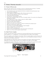
Dell 4.8 Rails and Cable Management 4.8.1 ReadyRails Sliding Rails ReadyRailsTM Sliding Rails for 4-post racks support the following: Toolless installation in 19‖ EIA-310-E compliant square or unthreaded round hole 4-post racks including all generations of Dell racks Full extension of the system out of the rack to allow serviceability of key internal components Optional cable management arm (CMA) except on racks less than 1m in depth, including Dell 4200 and 2400 racks Threaded 4-post racks require the ReadyRails™ static rails listed below or third-party offerings available through Dell Software and Peripherals 4.8.2 ReadyRails Static Rails ReadyRailsTM Static Rails for 4-post and 2-post racks support the following: Toolless installation in 19‖ EIA-310-E compliant square or unthreaded round hole 4-post racks including all generations of Dell racks Tooled installation in 19‖ EIA-310-E compliant threaded hole 4-post and 2-post racks See section 14 for more details. 4.9 Fans Six dual-rotor 40 mm fans are mounted in a fan assembly that is located in the chassis between the hard drive bay and the processors. Only five fans are populated in systems with a single processor configuration. Each fan has a connector that plugs directly into the planar. The R610 fans cannot be hot-swapped. There are six fan zones in the R610, with one zone for each system fan. The Embedded Server Management logic in the system controls and monitors the speed of the fans. A fan failure or over-temperature in the system results in a notification from iDRAC6. The R610 Power Supply Units do not have any integrated fans; they are cooled by the system fans in front of them. The system requires a power-supply blank (metal cover) in place of the empty power supply slot. System fan speed is pulse-width modulated. Redundant cooling is supported. To provide cooling when the system is off, both rotors in FAN_MOD1 run off Vaux power at a low speed setting when the ambient air temperature in the power supply passes a pre-defined threshold. The iDRAC controls the fan in AutoCool mode. 4.10 LCD Control Panel The LCD control panel is located on the front of the system chassis to provide user access to buttons, display, and I/O interfaces. See Figure 6. The control panel includes the following features: ACPI-compliant power button with an integrated green power LED (controlled by iDRAC6) 128x20 pixel LCD with controls: o Two navigation buttons o Select button o System ID button Non-maskable Interrupt (NMI) button (recessed) Ambient temperature sensor PowerEdge R610 Technical Guide 18
-
 1
1 -
2
-
3
-
4
-
5
-
6
-
7
-
8
-
9
-
10
-
11
-
12
-
 13
13 -
 14
14 -
 15
15 -
 16
16 -
 17
17 -
 18
18 -
 19
19 -
 20
20 -
 21
21 -
 22
22 -
 23
23 -
24
-
25
-
26
-
27
-
28
-
29
-
30
-
31
-
32
-
33
-
34
-
35
-
36
-
37
-
38
-
39
-
40
-
41
-
42
-
43
-
44
-
45
-
46
-
47
-
48
-
49
-
50
-
51
-
52
-
53
-
54
-
55
-
56
-
57
-
58
-
59
-
60
-
61
 |
 |
