Dell Force10 S5000 Getting Started Guide
Dell Force10 S5000 Manual
 |
View all Dell Force10 S5000 manuals
Add to My Manuals
Save this manual to your list of manuals |
Dell Force10 S5000 manual content summary:
- Dell Force10 S5000 | Getting Started Guide - Page 1
Dell Networking S5000 Getting Started Guide - Dell Force10 S5000 | Getting Started Guide - Page 2
of data and tells you how to avoid the problem. WARNING: A WARNING indicates a potential for property damage, personal injury, or death. © 2013 Dell Inc. Trademarks used in this text: Dell™, the Dell logo, Dell Boomi™, Dell Precision™ , OptiPlex™, Latitude™, PowerEdge™, PowerVault™, PowerConnect - Dell Force10 S5000 | Getting Started Guide - Page 3
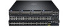
, refer to the FTOS Configuration Guide for the S5000 Switch, which is available on the Dell Support website at http://www.dell.com/support/manuals. Product Description The S5000 is part of Dell Networking's S-Series switches for Data Center Top of Rack (ToR) switches. The S5000 is purpose-built to - Dell Force10 S5000 | Getting Started Guide - Page 4
Modules (according to order) • Two Blanks • One RJ-45 to DB-9 female cable • Two AC or DC power cords for AC or DC units (country/region specific) • Getting Started Guide • Safety and Regulatory Information • Warranty and Support material. 5. Inspect the switch and accessories for damage. Important - Dell Force10 S5000 | Getting Started Guide - Page 5
power cables. 7. Install the fan modules. 8. Install the SFP+ and QSFP+ optics. 9. Supply power and power up the system. Hardware Overview This section contains information about device characteristics and modular hardware configurations for the S5000. The S5000 has the following physical dimensions - Dell Force10 S5000 | Getting Started Guide - Page 6
PSU 0) 2. Slot 1 (for Fan Module 0) 3. Slot 2 (for Fan Module 1) 4. Slot 3 (for PSU 1) 5. Grab Handles Power Supplies The S5000 supports two hot-swappable PSUs. NOTE: The PSUs must be installed at the customer site. The S5000 has SKUs that support the following configurations: • AC PSU with fan - Dell Force10 S5000 | Getting Started Guide - Page 7
10GbE mode. The S5000 supports the following possible modules: • 12-Port Ethernet Module (1G/10G speeds) (slot 0, 1, 2, or 3) • 12-Port Fibre Channel Module (2G/4G/8G Line Reference Guide and FTOS Configuration Guide for the S5000 Switch. As shown in the following figure, the S5000 includes LED - Dell Force10 S5000 | Getting Started Guide - Page 8
The following table lists the LED definitions for the S5000 system. Figure 5. System LEDs (Utility Panel) (AC Power Supplies installed) 1. Locator beacon LED 2. Alarm LED 3. System status LED 4. Master LED 5. Seven-segment display to identify - Dell Force10 S5000 | Getting Started Guide - Page 9
is booting • System in card problem state • Switch in Stacking Master mode OR Switch in Standalone mode • Switch in Stacking Standby mode • Switch in Stacking Member mode • Normal operation • Power not present • Normal operation • Power not present Figure 7. Module LEDs 1. Port locator beacon LED - Dell Force10 S5000 | Getting Started Guide - Page 10
No link or interface disabled • Link present and interface enabled (Ethernet module) • Port has activity • No activity • Module beacon/locator • Module is not powered up • Module is powered up • Problem detected with module Description • No activity • Port beacon/locator • Fibre Channel mode enabled - Dell Force10 S5000 | Getting Started Guide - Page 11
so you can read the LEDs. • AC/DC power cord reaches from the power outlet to the Utility-panel connector. • Switch is rack-mounted before you install the power supply modules. • Cabling is away from sources of electrical noise, such as radios, power lines, and fluorescent lighting. Make sure that - Dell Force10 S5000 | Getting Started Guide - Page 12
Chassis in a Rack or Cabinet To install the S5000 system, Dell Networking recommends completing the installation procedures in the order presented here. NOTE: Always handle the system and its components with care. Avoid dropping the S5000 chassis or its field replaceable units. NOTE: For proper - Dell Force10 S5000 | Getting Started Guide - Page 13
Read the safety instructions in your Safety, Environmental, and Regulatory information booklet before you begin. NOTE: The illustrations in this document are not intended to represent a specific switch. Installing the S5000 Chassis into a 4-Post Rack or Cabinet NOTE: Dell Networking recommends that - Dell Force10 S5000 | Getting Started Guide - Page 14
service uses in your area. The ground path must be permanent. Important Points to Remember for Installing an Ethernet Module • Installing and swapping of Ethernet modules or heel ground strap when handling the S5000 and its components. NOTE: For the Ethernet module, the part name and port number are - Dell Force10 S5000 | Getting Started Guide - Page 15
indicates that the Ethernet module does not support hot swapping during switch operations. Instead, you must power down the switch before removing and replacing an Ethernet module. A red color release latch indicates that the Ethernet module supports hot swapping during switch operations. Figure 11 - Dell Force10 S5000 | Getting Started Guide - Page 16
up, the system does not recognize the module. Online insertion of modules can result in a catastrophic failure. • The S5000 does not support the hot swapping of a Fibre Channel pluggable module during switch operations. Instead, you must power down the switch before removing and replacing a Fibre - Dell Force10 S5000 | Getting Started Guide - Page 17
as shown below. Figure 13. Part name and Port number on the Fibre Channel Module Handle 1. Part Name 2. Port Number Installing a Fibre Channel Module 1. Use the grab handle on the Fibre Channel module to slide it into the switch module slot. 2. Connect any network interface cables to the attached - Dell Force10 S5000 | Getting Started Guide - Page 18
information, refer to the System Logs chapters of the FTOS Command Line Reference Guide for the S5000 Switch and FTOS Configuration Guide for the S5000 Switch. WARNING: Although the switch can run on one PSU, Dell Networking highly recommends using two PSUs for full redundancy and proper cooling. If - Dell Force10 S5000 | Getting Started Guide - Page 19
error message appears and the system shuts down: 00:02:19: %S5000:0 %CHMGR-2-PSU_TYPE_AIRFLOW_MISMATCH: Mismatching PSU airflow detected. Unit 0 shall get -static bag. 2. Use the grab handle to slide the PSU into the switch PSU slot (install the PSU-exposed PCB edge connector first). The PSU slot - Dell Force10 S5000 | Getting Started Guide - Page 20
to DC power or installing grounds yourself. All electrical wiring must comply with applicable local or national codes and practices. Damage due to servicing that Dell Networking did not authorize is not covered by your warranty. 1. Strip the insulation from the end of the green/yellow wire, exposing - Dell Force10 S5000 | Getting Started Guide - Page 21
or the S5000 chassis. • The S5000 supports AC and DC power supplies with two air-flow directions (I/O to Utility and Utility to I/O). The S5000 does not support mixing Guide for the S5000 Switch and FTOS Configuration Guide for the S5000 Switch. WARNING: Although the switch can run on one PSU, Dell - Dell Force10 S5000 | Getting Started Guide - Page 22
PCB edge connector is at the bottom of the switch. Avoid installing the switch upside down. WARNING: Electrostatic discharge (ESD) damage can occur if components are mishandled. Always wear an ESDpreventive wrist or heel ground strap when handling the S5000 and its components. CAUTION: DO NOT mix - Dell Force10 S5000 | Getting Started Guide - Page 23
and the power source. CAUTION: Always disconnect the power cable before you service the power supply slots. CAUTION: Use the power supply cord as the Cables Add a ferrite bead to the DC power and return cables of the master module. Install the bead with a single loop. 1. Open ferrite bead with the - Dell Force10 S5000 | Getting Started Guide - Page 24
Figure 20. Installing the Ferrite Bead for DC Power and Return Cables 1. Ferrite Bead 2. DC Power and Return Cables 3. Leave approximately 4 to 5 inches of the DC power and return cables end protruding from the ferrite. 4. Snap the ferrite bead shut. Securing Power Cables 1. Bend the system power - Dell Force10 S5000 | Getting Started Guide - Page 25
four slots numbered from 0 to 3. Insert the fan modules in slots 1 and 2. • If a fan module fails, the system continues to operate without a significant of the FTOS Command Line Reference Guide for the S5000 Switch and FTOS Configuration Guide for the S5000 Switch. CAUTION: DO NOT mix airflow - Dell Force10 S5000 | Getting Started Guide - Page 26
to SFP+ Ports The S5000 supports splitting a single 40GbE QSFP+ port into four 10GbE SFP+ ports using one of the supported breakout cables. For a list of supported optics, refer to the S5000 data sheet: http://www.dell.com/us/enterprise/p/force10-s-series/pd. • Configure the system to recognize the - Dell Force10 S5000 | Getting Started Guide - Page 27
60. - portmode quad - Configure a 40GbE port to operate in S5000 unit. • The quad port must be in a default configuration module when the system is powered up, the system does not recognize the module. Online insertion of modules can result in a catastrophic failure. Dell S5000. the S5000 and its - Dell Force10 S5000 | Getting Started Guide - Page 28
settings are the same for both access ports. The S5000 supports bare metal provisioning (BMP). For information about how to configure BMP, refer to FTOS Configuration Guide for the S5000 Switch. Software Configuration Overview To configure the S5000, follow these steps: 1. Access the RJ-45/RS-232 - Dell Force10 S5000 | Getting Started Guide - Page 29
example, a PC). The pin assignments between the console and a DTE terminal server are as follows: Table 6. Pin Assignments Between the Console and a DTE Terminal Server S5000 Console Port Signal RJ-45 to RJ-45 Rollover Cable RJ-45 Pinout RJ-45 to RJ-45 Rollover Cable RJ-45 Pinout RJ-45 - Dell Force10 S5000 | Getting Started Guide - Page 30
need an Internet connection). For assistance, contact Dell Networking Technical Support. 3. Connect the USB-A end of cable configuration tasks using a Telnet connection from your management network. To configure other features and interfaces, refer to the FTOS Configuration Guide for the S5000 Switch - Dell Force10 S5000 | Getting Started Guide - Page 31
system. - 5 is for inputting a password that is already encrypted using an MD5 hash. Obtain the encrypted password from the configuration file of another Dell Networking system. Configuring a Host Name The host name appears in the prompt. The default host name is FTOS. Host names must start with - Dell Force10 S5000 | Getting Started Guide - Page 32
one command mode level. Default Configuration A version of FTOS is preloaded onto the S5000; however, the system is not configured when you power up for interface, use the switchport command in INTERFACE mode. You cannot configure switching or Layer 2 protocols, such as spanning tree protocol (STP), - Dell Force10 S5000 | Getting Started Guide - Page 33
in clear text. - 7 is for inputting a password that is already encrypted using a Type 7 hash. Obtaining the encrypted password from the configuration of another Dell Networking system. Creating a Port-based VLAN The default virtual local area network (VLAN) (VLAN 1) is part of the system startup - Dell Force10 S5000 | Getting Started Guide - Page 34
-based VLAN to tag it with that VLAN ID. 1. Access the INTERFACE VLAN mode of the VLAN to which you want to assign the interface. CONFIGURATION mode interface vlan vlan-id 2. Enable an interface to include the IEEE 802.1Q tag header. INTERFACE mode tagged interface To move untagged interfaces from - Dell Force10 S5000 | Getting Started Guide - Page 35
you have completed the hardware installation and software configuration for the S5000 system, you can connect to your company or equivalent type. Dispose of the batteries according to the manufacturer's instructions. Table 7. Chassis Physical Design Parameter Specifications Height 1.71 inches - Dell Force10 S5000 | Getting Started Guide - Page 36
Parameter Maximum thermal output Maximum Altitude Shock Table 9. Power Requirements Parameter AC Power supply DC Power supply Maximum current draw per system Maximum power consumption Specifications 2388 BTU/hr No performance degradation to 6600 ft Meets Bellcore Zone 4 earthquake requirements
-
 1
1 -
 2
2 -
 3
3 -
 4
4 -
 5
5 -
 6
6 -
 7
7 -
8
-
9
-
10
-
11
-
12
-
13
-
14
-
15
-
16
-
17
-
18
-
19
-
20
-
21
-
22
-
23
-
24
-
25
-
26
-
27
-
28
-
29
-
30
-
31
-
32
-
33
-
34
-
35
-
36
 |
 |

Dell Networking S5000
Getting Started Guide