Dell Force10 S5000 Getting Started Guide - Page 26
Installing the SFP+ and QSFP+ Optics, Splitting QSFP+ Ports to SFP+ Ports, Fan module 0/Slot 1
 |
View all Dell Force10 S5000 manuals
Add to My Manuals
Save this manual to your list of manuals |
Page 26 highlights
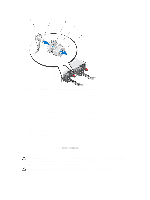
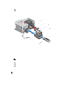
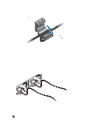
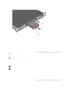
Figure 22. Installing a Fan Module 1. Fan module 0/Slot 1 2. Release latch Installing the SFP+ and QSFP+ Optics The S5000 has 48 small form-factor pluggable plus (SFP+) optical ports and four QSFP+ optical ports. For a list of supported optics, refer to the S5000 data sheet: http://www.dell.com/us/enterprise/p/force10-s-series/pd. CAUTION: ESD damage can occur if the components are mishandled. Always wear an ESD-preventive wrist or heel ground strap when handling the S5000 and its components. WARNING: When working with optical fibres, follow all the warning labels and always wear eye protection. Never look directly into the end of a terminated or unterminated fibre or connector as it may cause eye damage. 1. Position the optic so it is in the correct position. The optic has a key that prevents it from being inserted incorrectly. 2. Insert the optic into the port until it gently snaps into place. NOTE: Both rows of QSFP+ ports require that you install the 40GbE optics with the tabs facing up. NOTE: When you cable the ports, be sure not to interfere with the airflow from the small vent holes above and below the ports. Splitting QSFP+ Ports to SFP+ Ports The S5000 supports splitting a single 40GbE QSFP+ port into four 10GbE SFP+ ports using one of the supported breakout cables. For a list of supported optics, refer to the S5000 data sheet: http://www.dell.com/us/enterprise/p/force10-s-series/pd. • Configure the system to recognize the port mode change. CONFIGURATION mode 26
-
 1
1 -
2
-
3
-
4
-
5
-
6
-
7
-
8
-
9
-
10
-
11
-
12
-
13
-
14
-
15
-
16
-
17
-
18
-
19
-
20
-
 21
21 -
 22
22 -
 23
23 -
 24
24 -
 25
25 -
 26
26 -
 27
27 -
 28
28 -
 29
29 -
 30
30 -
 31
31 -
32
-
33
-
34
-
35
-
36
 |
 |
