Dell Force10 S55T Installing the S55 System
Dell Force10 S55T Manual
 |
View all Dell Force10 S55T manuals
Add to My Manuals
Save this manual to your list of manuals |
Dell Force10 S55T manual content summary:
- Dell Force10 S55T | Installing the S55 System - Page 1
Installing the S55 System - Dell Force10 S55T | Installing the S55 System - Page 2
damage to hardware or loss of data if instructions are not followed. WARNING: A WARNING indicates a potential for property damage, personal injury, or death. Information in this publication is subject to change without notice. © 2010 Dell Force10. All rights reserved. Reproduction of these materials - Dell Force10 S55T | Installing the S55 System - Page 3
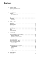
or cabinet 18 Attach ground cable 19 Insert optional modules 20 Install the SFP and SFP+ optics 21 Connect stacking ports (optional 21 Connect two S55s 22 Connect three or more S55s 23 Supply power and power up the system 24 Power up sequence 24 AC power 24 DC power 25 Hot-swap units in - Dell Force10 S55T | Installing the S55 System - Page 4
www.dell.com | support.dell.com Install an AC or DC power supply 27 Replace an AC or DC power supply 29 6 Fans Components 31 Install a fan module 31 Replace a fan module 32 7 Disposal 42 9 Technical Support The iSupport website 45 Accessing iSupport services 45 Contacting the Technical - Dell Force10 S55T | Installing the S55 System - Page 5
software configuration information and the FTOS Command Reference for the S55 for Command Line Interface (CLI) information. NOTE: The S55 requires FTOS version 8.3.5.0. Refer to the S55 Release Notes for information on upgrading the system, if necessary. Contact Dell Force10 Technical Support with - Dell Force10 S55T | Installing the S55 System - Page 6
www.dell.com | support.dell.com Related publications For more information about the S55, refer to the following documents: • FTOS Configuration Guide for the S55 system • FTOS Command Reference for the S55 system • FTOS Release Notes for the S55 system NOTE: For the most recent documentation and - Dell Force10 S55T | Installing the S55 System - Page 7
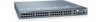
Introduction The Dell Force10 S55 is a high performance, high capacity, low cost, stackable, Layer 2 switch/Layer 3 router that supports 44 built-in 10/100/1000 Base-T ports, four SFP (small form-factor pluggable) ports, and two optional module slots, and optional 12G stacking module. The S55's PSU - Dell Force10 S55T | Installing the S55 System - Page 8
www.dell.com | support.dell.com Orderable S55 systems The S55 can be ordered in several different configurations. Optional modules are ordered separately. Hardware Catalog Number 44 port 10/100/1000 Base-T with 4 SFP ports and 2 expansion module slots S55T 44 port 10/100/1000 Base-T with 4 SFP - Dell Force10 S55T | Installing the S55 System - Page 9
through the CLI show commands and with SNMP traps. For details on those options, see the FTOS Command Reference for the S55 and the FTOS Configuration Guide for the S55. LED displays As shown in Figure 2-2, the S55 I/O panel contains several sets of LEDs. The Stacking ID LEDs is in the upper half - Dell Force10 S55T | Installing the S55 System - Page 10
www.dell.com | support.dell.com Figure 2-3. Stack ID hexidecimal Display • The system LEDs are (Figure 2-4): • Master (Stack Master status) • PSU1 (Power supply 1) • FAN1(Fan module 1) • ALM (System alarms) • SYS (System status) • PSU0 (Power supply 0) • FAN0 (Fan module 0) Figure 2-4. System LEDs - Dell Force10 S55T | Installing the S55 System - Page 11
Module (FAN0) LED Color/Display Off Green solid Off Green solid Yellow solid Off Green solid Yellow solid Off Yellow solid Red solid Off Yellow solid Red solid Off Green solid Yellow solid Off Green solid Yellow solid Description Non-master unit, or stand-alone unit Stack port The S55 System | 11 - Dell Force10 S55T | Installing the S55 System - Page 12
12 | The S55 System www.dell.com | support.dell.com - Dell Force10 S55T | Installing the S55 System - Page 13
. NOTE: Install the S55 unit into a rack or cabinet before installing any optional components. Site selection Dell Force10 equipment is intended for installation in restricted access areas. A restricted access area is one in which access can only be gained by service personnel through the use - Dell Force10 S55T | Installing the S55 System - Page 14
of the FTOS Command Reference and FTOS Configuration Guide. Power WARNING: Do not mix power supply types. The redundant power supplies must be the same type AC or DC. Use the appropriate power cord with the S55 chassis to connect the chassis to the applicable (AC or DC) power source. Power cords for - Dell Force10 S55T | Installing the S55 System - Page 15
disconnect device on the AC and the DC system; ensure that the socket-outlet is located/installed near the equipment and is easily accessible. Storing components If you do not install your system and components immediately, Dell Force10 recommends that you properly store the S55 and all optional - Dell Force10 S55T | Installing the S55 System - Page 16
16 | Site Preparations www.dell.com | support.dell.com - Dell Force10 S55T | Installing the S55 System - Page 17
components with care. Avoid dropping the S55 switch or its field replaceable units. 1 Install the S55 chassis in a rack or cabinet a Attach mounting brackets b Install chassis into rack or cabinet 2 Attach ground cable 3 Insert optional modules 4 Connect stacking ports (optional) 5 Supply power and - Dell Force10 S55T | Installing the S55 System - Page 18
.dell.com | support.dell. View from Chassis Front Screws Power Supply/Fan Module Connect to Rack/Cabinet (ears) Install chassis into switch into a two-post 19-inch equipment rack, using the already attached mounting brackets. Step Task 1 Dell Force10 recommends that one person hold the S55 - Dell Force10 S55T | Installing the S55 System - Page 19
are tightened firmly. PSU0 PSU1 Rack/Cabinet Post Rack Mounting ears Attach ground cable The S55 is shipped with 1 10-32 screws for attaching a ground cable to the chassis. The cable itself is not included. Dell Force10 recommends a 6AWG one-hole lug, #10 hole size, 63" spacing (not included in - Dell Force10 S55T | Installing the S55 System - Page 20
www.dell.com | support.dell.com Step Task (continued) 3 modules without powering down the system. CAUTION: Stacking modules can only be inserted into the lower optional module slot. Module Description 2-port 12G stacking module Catalog Number S55-12G-2ST 2-port 10G SFP+ optical module S55 - Dell Force10 S55T | Installing the S55 System - Page 21
to ensure that the cable is secure in the connector. Dell Force10 supports stacking connections for up to 12 S55 switches, to configure as a unified system. CAUTION: The S55 system does not stack with other S-Series systems. You can connect the switches while they are powered down or up. Both ring - Dell Force10 S55T | Installing the S55 System - Page 22
www.dell.com | support.dell.com The S55 supports stacking in either a ring or cascade topology. Dell Force10 recommends the ring topology when stacking S55 switches, to provide redundant connectivity. Figure 4-1. S55 stacking topology with 2-port 12G stacking module Switch 1 48 49 Switch 1 48 - Dell Force10 S55T | Installing the S55 System - Page 23
and top S55s. • Use the remaining cable to connect the top and bottom S55s by inserting one end of the cable into the open Stack Port 49 (or 48) of the bottom S55 and the other end of the cable into Stack Port 48 (or 49) of the top S55. Figure 4-3. 3 S55s with 2-port 12G stacking modules Install the - Dell Force10 S55T | Installing the S55 System - Page 24
www.dell.com | support.dell.com Supply power and power up the system Supply power to the S55 after they are mounted in a rack (or on a table) and the optional modules are installed. Dell Force10 recommends re-inspecting your system prior to powering up. Verify that: • the equipment is properly - Dell Force10 S55T | Installing the S55 System - Page 25
AC power connection DC power Connect the plug to each DC receptacle, making sure that the power cord is secure. As soon as the cable is connected between the S55 and the power source, the chassis is powered-up; there is no on/off switch. Figure 4-5. DC power connection Hot-swap units in a stack stack - Dell Force10 S55T | Installing the S55 System - Page 26
of the management unit. Use the show switch unit command to see the serial number of the designated unit. For details on removing a unit from a stack and other stacking commands, see the Stacking chapter in the FTOS Configuration Guide and the Stacking Commands chapter in the FTOS Command Reference - Dell Force10 S55T | Installing the S55 System - Page 27
the procedure to replace only a fan module. The S55 is orderable as an empty chassis (S55T) or with either AC or DC power. The S55T-AC/S55TAC-R system comes from the factory with 1 AC power supply and 2 fan modules installed in the chassis. The S55T-DC/S55T-DC-R system comes from the factory with - Dell Force10 S55T | Installing the S55 System - Page 28
.dell.com | support.dell.com NOTE: For a NEBS compliant installation, the AC power connections must use a surge protection device (SPD) to protect the AC power supplies from damage to excessive power line surges. NOTE: To comply with the GR-1089 Lightning Criteria for Equipment Interfacing with AC - Dell Force10 S55T | Installing the S55 System - Page 29
the power supply and the power source. Replace an AC or DC power supply NOTE: If a power supply fails, it must be completely replaced. There are no field servicable components in the module itself. Refer to Chapter 9, Technical Support to request a hardware replacement. To replace a power supply - Dell Force10 S55T | Installing the S55 System - Page 30
30 | Power Supplies www.dell.com | support.dell.com - Dell Force10 S55T | Installing the S55 System - Page 31
the system will shut down in 1 minute. In addition to the integrated fan/power supply modules, fan modules can be ordered separately and additional modules can be inserted in the chassis. The S55 supports two airflow direction options. Only a single direction can be used in a chassis; do not mix - Dell Force10 S55T | Installing the S55 System - Page 32
www.dell.com | support.dell.com Figure 6-1. Replacing the fan module PSU0 Optional Module Grab Handle To install a new fan module, follow the steps below: Step Task 1 Take the fan module out of the shipping box. 2 Using the grab handle, slide the module in to the bay. 3 Tighten the - Dell Force10 S55T | Installing the S55 System - Page 33
through the console port at I/O side of the switch. Access the RJ45 console port (RS-232) NOTE: Before starting this procedure, be sure you have a terminal emulation program already installed on your PC. The RS-232 console port is labeled on the S55 chassis. It is in the upper right-hand side - Dell Force10 S55T | Installing the S55 System - Page 34
Device Signal CTS DSR RxD GND GND TxD DTR RTS Access the USB-B console port The S55 has 2 management ports available for system access: a console port and a USB-B port. drivers for the USB device in use. Contact Dell Force10 Networks Technical Support for assistance. Step Task 1 Power on the - Dell Force10 S55T | Installing the S55 System - Page 35
the USB-B end of cable into the USB-B console port on the S55 ( 4 Power on the S55. 5 Install necessary USB device drivers (internet connection required). Contact Dell Force10 Networks Technical Support for assistance if necessary. 6 Open your terminal software emulation program to access - Dell Force10 S55T | Installing the S55 System - Page 36
36 | Access the console ports www.dell.com | support.dell.com - Dell Force10 S55T | Installing the S55 System - Page 37
S55 Specifications This chapter contains these major sections: • Chassis to 10,000 feet (3,048 meters) 10 to 85% non-condensing MIL-STD-810 AC Power Requirements Parameter Nominal Input Voltage Maximum AC Power Supply Input Current Maximum System Power Input Specifications 100 to 240 VAC, 47-63 - Dell Force10 S55T | Installing the S55 System - Page 38
ends. • Only reverse air flow configurations may be used in a NEBS compliant installation. Use only AC supply S55-PWR-AC-R, DC supply S55-PWR-DC-R and Fan Only S55-FAN-R, Systems S55-44TAC-R and S55-44T-DC-R. • Power supplies and fan modules must be fitted with the S55-PWR-FLTR kits. Fan filters - Dell Force10 S55T | Installing the S55 System - Page 39
AC input of the router. WARNING: Electrostatic discharge (ESD) damage can occur if components are mishandled. Always wear an ESD-preventive wrist or heel ground strap when handling the S55 in accordance to the instructions, it may cause harmful Dell Force10 option cards. This product has been tested - Dell Force10 S55T | Installing the S55 System - Page 40
equipment is used in a domestic environment, radio disturbance may arise. When such trouble occurs, the user may be required to take corrective actions. WARNING: AC Power cords are for use with Dell Force10 equipment only. Do not use Dell Force10 AC power cords with any unauthorized hardware. 40 - Dell Force10 S55T | Installing the S55 System - Page 41
Edition • EN 60825-1 Safety of Laser Products-Part 1: Equipment Classification Requirements and User's Guide • EN 60825-2 Safety of Laser Products-Part 2: Safety of Optical Fibre Communication Systems Japan: VCCI V3/ 2007.04 Class A • USA: FCC CFR47 Part 15, Subpart B, Class A S55 Specifications | 41 - Dell Force10 S55T | Installing the S55 System - Page 42
www.dell.com | support.dell.com Immunity • services in several countries to assist equipment owners in recycling their IT products. Waste Electrical and Electronic Equipment (WEEE) Directive for Recovery, Recycle and Reuse of IT and Telecommunications Products Dell Force10 switches S55 Specifications - Dell Force10 S55T | Installing the S55 System - Page 43
, as required by WEEE. For information on Dell Force10 product recycling offerings, see the WEEE Recycling instructions on iSupport at: https://www.force10networks.com/CSPortal20/Support/WEEEandRecycling.pdf. For more information, contact the Dell Force10 Technical Assistance Center (TAC). SD card - Dell Force10 S55T | Installing the S55 System - Page 44
www.dell.com | support.dell.com 2 Slide the top backwards until hazardous substances. For proper collection and treatment, contact your local Dell Force10 representative. Figure 8-9. The European WEEE Symbol For California: Perchlorate Practices for Perchlorate Materials. 44 | S55 Specifications - Dell Force10 S55T | Installing the S55 System - Page 45
patches, and open and manage your Technical Assistance Center (TAC) cases. Dell Force10 iSupport provides integrated, secure access to these services. Accessing iSupport services The URL for iSupport is http://www.force10networks.com/support/. You must have a userid and password to access iSupport - Dell Force10 S55T | Installing the S55 System - Page 46
Center How to Contact Dell Force10 TAC Information to Submit When Opening a Support Case Managing Your Case Downloading Software Updates Technical Documentation Contact Information Log in to iSupport at http://www.force10networks.com/support/ and select the Service Request tab. • Your name - Dell Force10 S55T | Installing the S55 System - Page 47
a Return Materials Authorization (RMA) number from TAC by opening a support case. Open a support case by: • Using the Create Service Request form on the iSupport page (see Contacting the Technical Assistance Center). • Contacting Dell Force10 directly by E-mail or by phone (see Contacting the - Dell Force10 S55T | Installing the S55 System - Page 48
48 | Technical Support www.dell.com | support.dell.com - Dell Force10 S55T | Installing the S55 System - Page 49
- Dell Force10 S55T | Installing the S55 System - Page 50
Printed in the U.S.A. www.dell.com | support.dell.com
-
 1
1 -
 2
2 -
 3
3 -
 4
4 -
 5
5 -
 6
6 -
 7
7 -
8
-
9
-
10
-
11
-
12
-
13
-
14
-
15
-
16
-
17
-
18
-
19
-
20
-
21
-
22
-
23
-
24
-
25
-
26
-
27
-
28
-
29
-
30
-
31
-
32
-
33
-
34
-
35
-
36
-
37
-
38
-
39
-
40
-
41
-
42
-
43
-
44
-
45
-
46
-
47
-
48
-
49
-
50
 |
 |

Installing the S55 System