Dell Inspiron N7110 Service Manual - Page 72
Replacing the System Board - fan replacement
 |
View all Dell Inspiron N7110 manuals
Add to My Manuals
Save this manual to your list of manuals |
Page 72 highlights
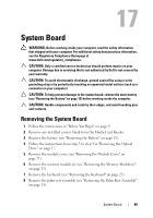
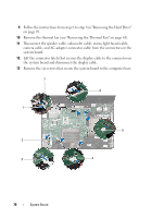
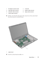
16 Remove the coin-cell battery (see "Removing the Coin-Cell Battery" on page 75). 17 Remove the thermal cooling assembly (see "Removing the Thermal Cooling Assembly" on page 81). 18 Remove the processor (see "Removing the Processor Module" on page 85). Replacing the System Board 1 Follow the instructions in "Before You Begin" on page 9. 2 Replace the processor (see "Replacing the Processor Module" on page 86). 3 Replace the thermal cooling assembly (see "Replacing the Thermal Cooling Assembly" on page 82). 4 Replace the coin-cell battery (see "Replacing the Coin-Cell Battery" on page 76). 5 Turn the system board assembly over. 6 Slide the connectors on the system board into the slots on the computer base. 7 Gently press the system board to connect the connector on the system board to the connector on the I/O board. 8 Replace the six screws that secure the system board to the computer base. 9 Connect the speaker cable, subwoofer cable, status-light board cable, camera cable, and AC-adapter cable to the connectors on the system board. 10 Slide the display cable into the connector on the system board and press down on the connector latch to secure the display cable to the connector on the system board. 11 Replace the thermal fan (see "Replacing the Thermal Fan" on page 66). 12 Follow the instructions from step 5 to step 7 in "Replacing the Hard Drive" on page 51. 13 Replace the palm-rest assembly (see "Replacing the Palm-Rest Assembly" on page 35). 14 Replace the keyboard (see "Replacing the Keyboard" on page 29). 72 System Board
-
 1
1 -
2
-
3
-
4
-
5
-
6
-
7
-
8
-
9
-
10
-
11
-
12
-
13
-
14
-
15
-
16
-
17
-
18
-
19
-
20
-
21
-
22
-
23
-
24
-
25
-
26
-
27
-
28
-
29
-
30
-
31
-
32
-
33
-
34
-
35
-
36
-
37
-
38
-
39
-
40
-
41
-
42
-
43
-
44
-
45
-
46
-
47
-
48
-
49
-
50
-
51
-
52
-
53
-
54
-
55
-
56
-
57
-
58
-
59
-
60
-
61
-
62
-
63
-
64
-
65
-
66
-
 67
67 -
 68
68 -
 69
69 -
 70
70 -
 71
71 -
 72
72 -
 73
73 -
 74
74 -
 75
75 -
 76
76 -
 77
77 -
78
-
79
-
80
-
81
-
82
-
83
-
84
-
85
-
86
-
87
-
88
-
89
-
90
-
91
-
92
-
93
-
94
-
95
-
96
-
97
-
98
-
99
-
100
-
101
-
102
-
103
-
104
-
105
-
106
-
107
-
108
-
109
-
110
-
111
-
112
-
113
-
114
-
115
-
116
 |
 |
