Dell Inspiron N7110 Service Manual - Page 92
Display Bezel
 |
View all Dell Inspiron N7110 manuals
Add to My Manuals
Save this manual to your list of manuals |
Page 92 highlights
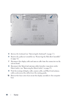
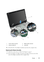
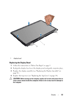
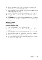
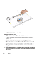
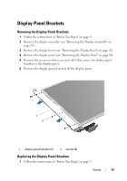
3 Route the display cable, camera cable, and Mini-Card antenna cables through the routing guides. 4 Connect the display cable and camera cable to the connectors on the system board. 5 Connect the Mini-Card antenna cables to the Mini-Card(s) (see "Replacing the Mini-Card(s)" on page 47). 6 Replace the palm-rest assembly (see "Replacing the Palm-Rest Assembly" on page 35). 7 Replace the keyboard (see "Replacing the Keyboard" on page 29). 8 Replace the two screws that secure the display assembly to the computer base. 9 Follow the instructions from step 4 to step 5 in "Replacing the Optical Drive" on page 19. 10 Replace the battery (see "Replacing the Battery" on page 16). CAUTION: Before turning on the computer, replace all screws and ensure that no stray screws remain inside the computer. Failure to do so may result in damage to the computer. Display Bezel Removing the Display Bezel 1 Follow the instructions in "Before You Begin" on page 9. 2 Remove the top cover (see "Removing the Top Cover" on page 13). 3 Remove the display assembly (see "Removing the Display Assembly" on page 89). CAUTION: The display bezel is extremely fragile. Be careful when removing it to prevent damaging the display bezel. 4 Using your fingertips, carefully pry up the inside edge of the display bezel. 5 Remove the display bezel. 92 Display
-
 1
1 -
2
-
3
-
4
-
5
-
6
-
7
-
8
-
9
-
10
-
11
-
12
-
13
-
14
-
15
-
16
-
17
-
18
-
19
-
20
-
21
-
22
-
23
-
24
-
25
-
26
-
27
-
28
-
29
-
30
-
31
-
32
-
33
-
34
-
35
-
36
-
37
-
38
-
39
-
40
-
41
-
42
-
43
-
44
-
45
-
46
-
47
-
48
-
49
-
50
-
51
-
52
-
53
-
54
-
55
-
56
-
57
-
58
-
59
-
60
-
61
-
62
-
63
-
64
-
65
-
66
-
67
-
68
-
69
-
70
-
71
-
72
-
73
-
74
-
75
-
76
-
77
-
78
-
79
-
80
-
81
-
82
-
83
-
84
-
85
-
86
-
 87
87 -
 88
88 -
 89
89 -
 90
90 -
 91
91 -
 92
92 -
 93
93 -
 94
94 -
 95
95 -
 96
96 -
 97
97 -
98
-
99
-
100
-
101
-
102
-
103
-
104
-
105
-
106
-
107
-
108
-
109
-
110
-
111
-
112
-
113
-
114
-
115
-
116
 |
 |
