Dell Latitude 3440 Owners Manual - Page 33
Installing the Display Bezel, Removing the Display Panel
 |
View all Dell Latitude 3440 manuals
Add to My Manuals
Save this manual to your list of manuals |
Page 33 highlights
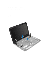
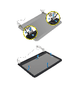
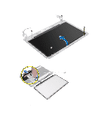
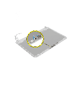
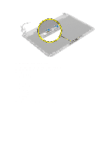
Installing the Display Bezel 1. Align the display bezel in place and snap it in place. 2. Align the hinge covers on display assembly and snap the hinge covers on its place. 3. Install: a) display assembly b) system board c) palmrest d) keyboard e) optical drive f) hard drive g) memory module h) WLAN card i) access panel j) SD card k) battery 4. Follow the procedures in After Working Inside Your Computer. Removing the Display Panel 1. Follow the procedures in Before Working Inside Your Computer. 2. Remove: a) battery b) SD card c) access panel d) memory module e) WLAN card f) hard drive g) optical drive h) keyboard i) palmrest j) system board k) display assembly l) display bezel m) display hinges 3. Remove the screws that secure the display panel to the display assembly. Lift the display panel and flip to access the display cable. 33
-
 1
1 -
2
-
3
-
4
-
5
-
6
-
7
-
8
-
9
-
10
-
11
-
12
-
13
-
14
-
15
-
16
-
17
-
18
-
19
-
20
-
21
-
22
-
23
-
24
-
25
-
26
-
27
-
 28
28 -
 29
29 -
 30
30 -
 31
31 -
 32
32 -
 33
33 -
 34
34 -
 35
35 -
 36
36 -
 37
37 -
 38
38 -
39
-
40
-
41
-
42
-
43
-
44
-
45
-
46
-
47
-
48
-
49
-
50
-
51
-
52
-
53
-
54
-
55
 |
 |