Dell Latitude E5530 User Manual - Page 37
Installing the Right Support Frame, Removing the Modem Card - 3 displays
 |
View all Dell Latitude E5530 manuals
Add to My Manuals
Save this manual to your list of manuals |
Page 37 highlights
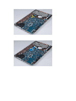
Installing the Right Support Frame 1. Place the right support frame on the computer. 2. Tighten the screws to secure the right support frame to the computer. 3. Install: a) display assembly b) palmrest c) processor door d) hard drive e) optical drive f) keyboard g) keyboard trim h) bottom doorl i) battery j) SD memory card 4. Follow the procedures in After Working Inside Your Computer. Removing the Modem Card 1. Follow the procedures in Before Working Inside Your Computer. 2. Remove: a) SD memory card b) battery c) bottom door d) keyboard trim e) keyboard f) optical drive g) hard drive h) processor door i) palmrest j) display assembly k) right support frame 3. Remove the screw that secures the modem card to the computer. 4. Lift the modem card to disengage from the connector on the back of the card. 5. Disconnect the RJ11 cable from the modem card. 6. Lift the modem card from the computer. 37
-
 1
1 -
2
-
3
-
4
-
5
-
6
-
7
-
8
-
9
-
10
-
11
-
12
-
13
-
14
-
15
-
16
-
17
-
18
-
19
-
20
-
21
-
22
-
23
-
24
-
25
-
26
-
27
-
28
-
29
-
30
-
31
-
 32
32 -
 33
33 -
 34
34 -
 35
35 -
 36
36 -
 37
37 -
 38
38 -
 39
39 -
 40
40 -
 41
41 -
 42
42 -
43
-
44
-
45
-
46
-
47
-
48
-
49
-
50
-
51
-
52
-
53
-
54
-
55
-
56
-
57
-
58
-
59
-
60
-
61
-
62
-
63
-
64
-
65
-
66
-
67
-
68
-
69
-
70
-
71
 |
 |
