Dell Latitude E6400 ATG Service Manual - Page 41
Removing the Microphone Board, Replacing the Microphone Board
 |
View all Dell Latitude E6400 ATG manuals
Add to My Manuals
Save this manual to your list of manuals |
Page 41 highlights
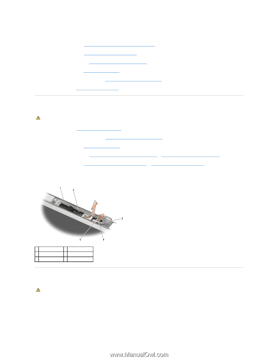
2. Replace the two M2.5 x 5-mm screws on the right hinge and the two M2.5 x 5-mm screws on the left hinge. 3. Replace the display panel (see Replacing the Display Panel and Brackets (E6400 ATG)). 4. Replace the display bezel (see Replacing the Display Bezel (E6400 ATG)). 5. Replace the display assembly (see Replacing the Display Assembly (E6400 ATG)). 6. Replace the hinge covers (see Replacing the Hinge Covers). 7. Replace the bottom of the base assembly (see Replacing the Bottom of the Base Assembly). 8. Follow the procedures in After Working on Your Computer. Removing the Microphone Board CAUTION: Before you begin the following procedure, follow the safety instructions that shipped with your computer. 1. Follow the instructions in Before Working on Your Computer. 2. Remove the bottom of the base assembly (see Removing the Bottom of the Base Assembly). 3. Remove the hinge covers (see Removing the Hinge Covers). 4. Remove the display assembly (see Removing the Display Assembly (E6400 and M2400) or Removing the Display Assembly (E6400 ATG)). 5. Remove the display bezel (see Removing the Display Bezel (E6400 and M2400) or Removing the Display Bezel (E6400 ATG)). 6. Lift the small connector lever on the microphone cable. 7. Loosen the captive screw, and carefully lift the microphone board up at an angle and disconnect the microphone cable. 1 display cover 2 microphone board 3 captive screw 4 connector lever 5 microphone cable Replacing the Microphone Board CAUTION: Before you begin the following procedure, follow the safety instructions that shipped with your computer. 1. Slide the cable connector of the microphone cable into the connector on the microphone board. 2. Close the lever on the connector on the microphone board. 3. Angle in and align the microphone board with the notch on the display cover.
-
 1
1 -
2
-
3
-
4
-
5
-
6
-
7
-
8
-
9
-
10
-
11
-
12
-
13
-
14
-
15
-
16
-
17
-
18
-
19
-
20
-
21
-
22
-
23
-
24
-
25
-
26
-
27
-
28
-
29
-
30
-
31
-
32
-
33
-
34
-
35
-
 36
36 -
 37
37 -
 38
38 -
 39
39 -
 40
40 -
 41
41 -
 42
42 -
 43
43 -
 44
44 -
 45
45 -
 46
46 -
47
-
48
-
49
-
50
-
51
-
52
-
53
-
54
-
55
-
56
-
57
-
58
-
59
-
60
-
61
-
62
-
63
-
64
-
65
-
66
-
67
-
68
-
69
-
70
-
71
-
72
-
73
-
74
-
75
-
76
-
77
-
78
-
79
-
80
-
81
-
82
-
83
-
84
-
85
-
86
-
87
-
88
-
89
-
90
-
91
-
92
-
93
-
94
-
95
-
96
-
97
-
98
-
99
 |
 |