Dell OptiPlex 5080 Small Form Factor Service Manual
Dell OptiPlex 5080 Small Form Factor Manual
 |
View all Dell OptiPlex 5080 Small Form Factor manuals
Add to My Manuals
Save this manual to your list of manuals |
Dell OptiPlex 5080 Small Form Factor manual content summary:
- Dell OptiPlex 5080 Small Form Factor | Service Manual - Page 1
OptiPlex 5080 Small Form Factor Service Manual Regulatory Model: D15S Regulatory Type: D15S001 May 2020 Rev. A00 - Dell OptiPlex 5080 Small Form Factor | Service Manual - Page 2
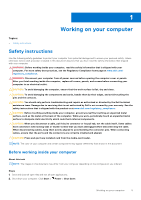
of data and tells you how to avoid the problem. WARNING: A WARNING indicates a potential for property damage, personal injury, or death. © 2020 Dell Inc. or its subsidiaries. All rights reserved. Dell, EMC, and other trademarks are trademarks of Dell Inc. or its subsidiaries. Other trademarks may be - Dell OptiPlex 5080 Small Form Factor | Service Manual - Page 3
instructions...5 Before working inside your computer...5 Safety precautions...6 Electrostatic discharge-ESD protection...6 ESD field service 430...12 System management features...12 Dell Client Command Suite for In-Band systems management 13 Chapter 3: Field service information 14 Side cover...14 - Dell OptiPlex 5080 Small Form Factor | Service Manual - Page 4
...36 Removing the processor...38 System board...39 Removing the system board...39 Installing the system board...42 Chapter 4: Troubleshooting...47 Dell SupportAssist Pre-boot System Performance Check diagnostics 47 Running the SupportAssist Pre-Boot System Performance Check 47 Diagnostic LED - Dell OptiPlex 5080 Small Form Factor | Service Manual - Page 5
and the contacts. CAUTION: You should only perform troubleshooting and repairs as authorized or directed by the Dell technical assistance team. Damage due to servicing that is not authorized by Dell is not covered by your warranty. See the safety instructions that is shipped with the product or at - Dell OptiPlex 5080 Small Form Factor | Service Manual - Page 6
any disassembly instructions. Observe the of getting electrocuted. Standby power Dell products with standby power must be is done through the use of a field service electrostatic discharge (ESD) kit. When connecting a not be obvious, such as intermittent problems or a shortened product life span - Dell OptiPlex 5080 Small Form Factor | Service Manual - Page 7
of damage to recognize and troubleshoot is the intermittent (also ESD mat, and the hardware is known as bonding. Use only Field Service kits with a wrist strap, mat, and bonding wire. Never use wireless parts or parts to be returned to Dell, it is critical to place these parts in anti-static bags - Dell OptiPlex 5080 Small Form Factor | Service Manual - Page 8
grounding wrist strap and protective anti-static mat at all times when servicing Dell products. In addition, it is critical that technicians keep sensitive parts separate from all insulator parts while performing service and that they use anti-static bags for transporting sensitive components. After - Dell OptiPlex 5080 Small Form Factor | Service Manual - Page 9
USB type-C Alt mode: 4096 x 2304 @60 Hz ● Option VGA: 1920 x 1200 @60 Hz ● Option HDMI2.0: 4096 x 2160 @60 Hz Up to three displays supported ● Two motherboard integrated DP1.4 HBR2 + One video option (VGA/DP1.4 HBR2/HDMI2.0/USB3.2 Gen2 type-C Alt-mode) Two MB integrated DP1.4 HBR2 + One video option - Dell OptiPlex 5080 Small Form Factor | Service Manual - Page 10
Shader model Open CL Open GL GPU memory interface PCIe bus Display support Graphics memory configuration Graphics memory clock speed Active fan sink Slot number PCB form factor PCB layer PCB solder mask Bracket form factor Maximum resolution Values 902 MHz 12.0 5.0 1.1 4.5 64 bit PCIe 3.0 x8 One - Dell OptiPlex 5080 Small Form Factor | Service Manual - Page 11
Shader model Open CL Open GL GPU memory interface PCIe bus Display support Graphics memory configuration Graphics memory clock speed Active fan sink Slot number PCB form factor PCB layer PCB solder mask Bracket form factor Maximum resolution Power consumption 3D mark performance Values 1.2 GHz 12 - Dell OptiPlex 5080 Small Form Factor | Service Manual - Page 12
support Graphics memory configuration Graphics memory clock speed Active fan sink Slot number PCB form factor PCB layer PCB solder mask Bracket form factor is connected to a network so that it can be managed. The Dell Client Command Suite of tools can be leveraged individually or with a systems - Dell OptiPlex 5080 Small Form Factor | Service Manual - Page 13
Client Command Suite is a free toolkit available for download, for all Latitude Rugged tablets at dell.com/support, automates and streamlines systems management tasks, saving time, money, and resources. It consists of the following modules that can be used independently, or with a variety - Dell OptiPlex 5080 Small Form Factor | Service Manual - Page 14
3 Field service information Topics: • Side cover • Front bezel • Hard-drive assembly • Solid-state drive • WLAN card • Slim optical-drive • Heat sink • Coin- images indicate the location of the side panels and provide a visual representation of the removal procedure. 14 Field service information - Dell OptiPlex 5080 Small Form Factor | Service Manual - Page 15
Steps 1. Press down on the release latch until your hear a click. 2. Slide the side cover towards the back of the system. 3. Lift the side cover from the system. Field service information 15 - Dell OptiPlex 5080 Small Form Factor | Service Manual - Page 16
installation procedure. About this task The following image indicates the location of the side panels and provides a visual representation of the installation procedure. 16 Field service information - Dell OptiPlex 5080 Small Form Factor | Service Manual - Page 17
of the removal procedure. Steps 1. Pry the retention tabs to release the front bezel from the system. 2. Remove the front bezel from the system. Field service information 17 - Dell OptiPlex 5080 Small Form Factor | Service Manual - Page 18
working inside your computer. Hard-drive assembly Removing the 2.5 in. hard drive assembly Prerequisites 1. Follow the procedure in before working inside your computer. 18 Field service information - Dell OptiPlex 5080 Small Form Factor | Service Manual - Page 19
drive assembly. About this task The following images indicate the location of the hard drive cage and provide a visual representation of the removal procedure. Field service information 19 - Dell OptiPlex 5080 Small Form Factor | Service Manual - Page 20
procedure. About this task The following image indicates the location of the 2.5 in. hard drive and provides a visual representation of the installation procedure. 20 Field service information - Dell OptiPlex 5080 Small Form Factor | Service Manual - Page 21
installation procedure. About this task The following image indicates the location of the hard drive cage and provides a visual representation of the installation procedure. Field service information 21 - Dell OptiPlex 5080 Small Form Factor | Service Manual - Page 22
assembly. About this task The following images indicate the location of the solid-state drive and provide a visual representation of the removal procedure. 22 Field service information - Dell OptiPlex 5080 Small Form Factor | Service Manual - Page 23
installation procedure. About this task The following image indicates the location of the solid-state drive and provides a visual representation of the installation procedure. Field service information 23 - Dell OptiPlex 5080 Small Form Factor | Service Manual - Page 24
assembly. About this task The following images indicate the location of the solid-state drive and provide a visual representation of the removal procedure. 24 Field service information - Dell OptiPlex 5080 Small Form Factor | Service Manual - Page 25
installation procedure. About this task The following image indicates the location of the solid-state drive and provides a visual representation of the installation procedure. Field service information 25 - Dell OptiPlex 5080 Small Form Factor | Service Manual - Page 26
drive assembly. About this task The following images indicate the location of the wireless card and provide a visual representation of the removal procedure. 26 Field service information - Dell OptiPlex 5080 Small Form Factor | Service Manual - Page 27
the installation procedure. About this task The following image indicates the location of the wireless card and provides a visual representation of the installation procedure. Field service information 27 - Dell OptiPlex 5080 Small Form Factor | Service Manual - Page 28
1. Install the 2.5 in. hard drive assembly. 2. Install the front bezel. 3. Install the side cover. 4. Follow the procedure in after working inside your computer. 28 Field service information - Dell OptiPlex 5080 Small Form Factor | Service Manual - Page 29
drive/ hard drive module. 2. Slide the optical drive out of the optical drive/ hard drive module. 3. Optical drive unit. 4. Optical drive/ hard drive module. Field service information 29 - Dell OptiPlex 5080 Small Form Factor | Service Manual - Page 30
Optical drive unit until it clicks in place. Next steps 1. Install the Side cover. 2. Follow the procedure in after working inside your computer. 30 Field service information - Dell OptiPlex 5080 Small Form Factor | Service Manual - Page 31
installation procedure. About this task The following image indicates the location of the VR heat sink and provides a visual representation of the installation procedure. Field service information 31 - Dell OptiPlex 5080 Small Form Factor | Service Manual - Page 32
bezel. About this task The following images indicate the location of the coin-cell battery and provide a visual representation of the removal procedure. 32 Field service information - Dell OptiPlex 5080 Small Form Factor | Service Manual - Page 33
installation procedure. About this task The following image indicates the location of the coin-cell battery and provides a visual representation of the installation procedure. Field service information 33 - Dell OptiPlex 5080 Small Form Factor | Service Manual - Page 34
drive assembly. About this task The following images indicate the location of the memory modules and provide a visual representation of the removal procedure. 34 Field service information - Dell OptiPlex 5080 Small Form Factor | Service Manual - Page 35
memory modules Prerequisites About this task The following image indicates the location of the memory modules and provides a visual representation of the installation procedure. Field service information 35 - Dell OptiPlex 5080 Small Form Factor | Service Manual - Page 36
the installation procedure. About this task The following image indicates the location of the processor and provides a visual representation of the installation procedure. 36 Field service information - Dell OptiPlex 5080 Small Form Factor | Service Manual - Page 37
it. Next steps 1. Install the heat-sink. 2. Install the front bezel. 3. Install the side cover. 4. Follow the procedure in after working inside your computer. Field service information 37 - Dell OptiPlex 5080 Small Form Factor | Service Manual - Page 38
processor, do not touch any of the pins inside the socket or allow any objects to fall on the pins in the socket. 38 Field service information - Dell OptiPlex 5080 Small Form Factor | Service Manual - Page 39
. 9. Remove the processor. About this task The following images indicate the location of the system board and provide a visual representation of the removal procedure. Field service information 39 - Dell OptiPlex 5080 Small Form Factor | Service Manual - Page 40
40 Field service information - Dell OptiPlex 5080 Small Form Factor | Service Manual - Page 41
Field service information 41 - Dell OptiPlex 5080 Small Form Factor | Service Manual - Page 42
installation procedure. About this task The following image indicates the location of the system board and provides a visual representation of the installation procedure. 42 Field service information - Dell OptiPlex 5080 Small Form Factor | Service Manual - Page 43
Field service information 43 - Dell OptiPlex 5080 Small Form Factor | Service Manual - Page 44
44 Field service information - Dell OptiPlex 5080 Small Form Factor | Service Manual - Page 45
the SATA cables. 11. Reconnect the SATA power cable. 12. Reconnect the internal speaker cables. Next steps 1. Install the processor. 2. Install the memory modules. Field service information 45 - Dell OptiPlex 5080 Small Form Factor | Service Manual - Page 46
3. Install the heat-sink. 4. Install the WLAN card. 5. Install the solid-state drive. 6. Install the hard drive assembly. 7. Install the front bezel. 8. Install the side cover. 9. Follow the procedure in after working inside your computer. 46 Field service information - Dell OptiPlex 5080 Small Form Factor | Service Manual - Page 47
Troubleshooting Topics: • Dell SupportAssist Pre-boot System Performance Check diagnostics • Diagnostic LED behavior • Diagnostic error messages • System error messages • WiFi power cycle Dell ● View error messages that inform you of problems encountered during testing NOTE: Some tests for specific - Dell OptiPlex 5080 Small Form Factor | Service Manual - Page 48
found ● Flash latest BIOS version but invalid ● If problem persists, replace the system board. Power rail failure ● EC ran into power sequencing failure. ● If problem persists, replace the system board. SBIOS Flash corruption ● Flash corruption detected by SBIOS 48 Troubleshooting - Dell OptiPlex 5080 Small Form Factor | Service Manual - Page 49
reply to HECI message ● If problem persists, replace the system board. ERROR READING PCMCIA CARD EXTENDED MEMORY SIZE HAS CHANGED THE FILE BEING primary cache internal to the microprocessor has failed. Contact Dell The optical drive does not respond to commands from the Troubleshooting 49 - Dell OptiPlex 5080 Small Form Factor | Service Manual - Page 50
computer, reinstall the hard drive, and restart the computer. If the problem persists, try another drive. Run the Hard Disk Drive tests in Dell Diagnostics. HARD-DISK DRIVE READ FAILURE The hard drive may be the error message still appears, see the software documentation. 50 Troubleshooting - Dell OptiPlex 5080 Small Form Factor | Service Manual - Page 51
hard drive. See Windows Help and Support for instructions (click Start > Help and Support). If a large number of sectors are supports the system configuration settings may require recharging. Connect your computer to an electrical outlet to charge the battery. If the problem persists, Contact Dell - Dell OptiPlex 5080 Small Form Factor | Service Manual - Page 52
nnnn]. For help in resolving this problem, please note this checkpoint and contact Dell Technical Support The computer failed to complete the . The following procedure provides the instructions on how to conduct a WiFi power cycle: NOTE: Some ISPs (Internet Service Providers) provide a modem/router - Dell OptiPlex 5080 Small Form Factor | Service Manual - Page 53
. Availability varies by country and product, and some services may not be available in your area. To contact Dell for sales, technical support, or customer service issues: Steps 1. Go to Dell.com/support. 2. Select your support category. 3. Verify your country or region in the Choose a Country
-
 1
1 -
 2
2 -
 3
3 -
 4
4 -
 5
5 -
 6
6 -
 7
7 -
8
-
9
-
10
-
11
-
12
-
13
-
14
-
15
-
16
-
17
-
18
-
19
-
20
-
21
-
22
-
23
-
24
-
25
-
26
-
27
-
28
-
29
-
30
-
31
-
32
-
33
-
34
-
35
-
36
-
37
-
38
-
39
-
40
-
41
-
42
-
43
-
44
-
45
-
46
-
47
-
48
-
49
-
50
-
51
-
52
-
53
 |
 |

OptiPlex 5080 Small Form Factor
Service Manual
Regulatory Model: D15S
Regulatory Type: D15S001
May 2020
Rev. A00