Dell OptiPlex 960 Technology Guide - Page 7
Back Panel Connectors, System Board - wireless card
 |
View all Dell OptiPlex 960 manuals
Add to My Manuals
Save this manual to your list of manuals |
Page 7 highlights
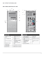
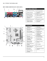
DELL™ OPTIPLEX™ 960 TECHNICAL GUIDE DESKTOP COMPUTER (DT) VIEW (CONT.) BACK PANEL CONNECTORS 1 PS/2 Mouse Connector 8 Line-out Connector 2 Parallel Connector 9 Line-in/Microphone Connctor 3 Serial Connector 10 USB 2.0 Connectors (6) 4 Link Integrity Light 11 VGA Connector 5 Network Adapter Connector 12 eSATA Connector 6 Network Activity Light 13 DisplayPort Connector 7 Wireless Network Adapter (optional) 14 PS/2 Keyboard Connector SYSTEM BOARD 1 Fan Connector (FAN_CPU) 13 PCI Express x16 Connector (SLOT1) 2 Processor Connector (CPU) 14 PCI Connector (SLOT2) Processor Power 3 Connector (12VPOWER) Memory Module 4 Connectors (DIMM_1, DIMM_2, DIMM_3, DIMM_4) 5 SATA Connectors (3) 6 Password Jumper (PSWD) 7 Internal USB Connector (FLEX_USB) 15 PCI Connector (SLOT3) 16 PCI Express x1 Connector (SLOT4) 17 RTC Reset Jumper Pins 18 Battery Socket (BATTERY) Riser Connector (uses 19 PCI-E port/SLOT1 and PCI port/SLOT2) 8 Service Mode Jumper (SERVICE_MODE) 20 Floppy Connector (DSKT) 9 Power Connect (POWER) 21 Internal Speaker (INT_SPKR) 10 Front Panel Connector (FRONTPANEL) 22 Connector for Optional Wireless Card 11 Serial Connector 23 Front Panel Thermal Sensor 12 Intrusion Switch Connector (INTRUDER) 7
-
 1
1 -
 2
2 -
 3
3 -
 4
4 -
 5
5 -
 6
6 -
 7
7 -
 8
8 -
 9
9 -
 10
10 -
 11
11 -
 12
12 -
13
-
14
-
15
-
16
-
17
-
18
-
19
-
20
-
21
-
22
-
23
-
24
-
25
-
26
-
27
-
28
-
29
-
30
-
31
-
32
-
33
-
34
-
35
-
36
-
37
-
38
-
39
-
40
 |
 |
