Dell OptiPlex GX100 User Guide - Page 51
System Board Labels, Rotating the Power Supply Away From the System Board Mini Tower Chassis Only
 |
View all Dell OptiPlex GX100 manuals
Add to My Manuals
Save this manual to your list of manuals |
Page 51 highlights
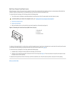
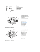
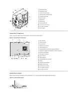
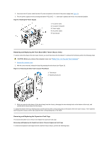
Jumpers are small blocks on a circuit board with two or more pins emerging from them. Plastic plugs containing a wire fit down over the pins. The wire connects the pins and creates a circuit. To change a jumper setting, pull the plug off its pin(s) and carefully fit it down onto the pin(s) indicated. NOTICE: Make sure your system is turned off and unplugged before you change a jumper setting. Otherwise, damage to your system or unpredictable results may occur. Table 1. System-Board Jumper Settings Jumper PSWD jumpered Setting (default) Description System password features are enabled. unjumpered System password features are disabled. System Board Labels Table 2 lists the labels for light-emitting diode (LED) indicators, connectors, and sockets on the system board, and it gives a brief description of their functions. Table 2. System Board Indicators, Connectors, and Sockets Connector or Socket AUX_LED B1 DIMM_x DSKT ENET FAN IDEn INTRUSION KYBD MICROPROCESSOR MONITOR MOUSE PANEL PARALLEL POWER_1 POWER_2 RISER SERIALn USB Description Auxiliary power indicator Battery socket Dual in-line memory module (DIMM) socket Diskette/tape drive interface connector Integrated network interface controller (NIC) connector Microprocessor fan connector EIDE interface connector Chassis intrusion switch connector Keyboard connector Microprocessor connector Video connector Mouse connector Control panel connector Parallel port connector; sometimes referred to as LPT1 Main power input connector 3.3-volt (V) power input connector Riser board connector Serial port connectors Universal Serial Bus (USB) connectors Rotating the Power Supply Away From the System Board (Mini Tower Chassis Only) To access some components on the system board, you may have to rotate the mini tower chassis system power supply out of the way. To rotate the power supply, perform the following steps. CAUTION: Before you remove the computer cover, see "Safety First-For You and Your Computer." 1. Remove the computer cover as instructed in "Removing and Replacing the Computer Cover."
-
 1
1 -
2
-
3
-
4
-
5
-
6
-
7
-
8
-
9
-
10
-
11
-
12
-
13
-
14
-
15
-
16
-
17
-
18
-
19
-
20
-
21
-
22
-
23
-
24
-
25
-
26
-
27
-
28
-
29
-
30
-
31
-
32
-
33
-
34
-
35
-
36
-
37
-
38
-
39
-
40
-
41
-
42
-
43
-
44
-
45
-
 46
46 -
 47
47 -
 48
48 -
 49
49 -
 50
50 -
 51
51 -
 52
52 -
 53
53 -
 54
54 -
 55
55 -
 56
56 -
57
-
58
-
59
-
60
-
61
-
62
-
63
-
64
-
65
-
66
-
67
-
68
-
69
-
70
-
71
-
72
-
73
-
74
-
75
-
76
-
77
-
78
-
79
-
80
-
81
-
82
-
83
-
84
-
85
-
86
-
87
-
88
-
89
-
90
-
91
-
92
-
93
-
94
-
95
-
96
-
97
-
98
-
99
-
100
-
101
-
102
-
103
-
104
-
105
-
106
-
107
 |
 |
