Dell OptiPlex Gs Reference and Installation Guide (.pdf)
Dell OptiPlex Gs Manual
 |
View all Dell OptiPlex Gs manuals
Add to My Manuals
Save this manual to your list of manuals |
Dell OptiPlex Gs manual content summary:
- Dell OptiPlex Gs | Reference and Installation Guide (.pdf) - Page 1
Dell® OptiPlex® Gs and Gs+ Low-Profile Systems REFERENCE AND INSTALLATION GUIDE ® - Dell OptiPlex Gs | Reference and Installation Guide (.pdf) - Page 2
any manner whatsoever without the written permission of Dell Computer Corporation is strictly forbidden. Trademarks used in this text: Dell, the DELL logo, and OptiPlex are registered trademarks and DellWare is a registered service mark of Dell Computer Corporation; Intel and Pentium are registered - Dell OptiPlex Gs | Reference and Installation Guide (.pdf) - Page 3
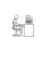
your computer. If the computer gets wet, consult your Diagnostics and Troubleshooting Guide. • Do not push any objects into the openings of your computer. in front of you as you work. Special shelves are available (from Dell and other sources) to help you correctly position your keyboard. • Set - Dell OptiPlex Gs | Reference and Installation Guide (.pdf) - Page 4
• Keep your forearms horizontal with your wrists in a neutral, comfortable position while using the keyboard or mouse. • Always leave space to rest your hands while using the keyboard or mouse. • Let your upper arms hang naturally at your sides. • Sit erect, with your feet resting on the floor and - Dell OptiPlex Gs | Reference and Installation Guide (.pdf) - Page 5
note of these safety guidelines when appropriate: • Do not attempt to service the computer system your- self, except as explained in this guide and elsewhere in Dell documentation. Always follow installation and servicing instructions closely. • When removing a component from the system board or - Dell OptiPlex Gs | Reference and Installation Guide (.pdf) - Page 6
viii - Dell OptiPlex Gs | Reference and Installation Guide (.pdf) - Page 7
About This Guide This guide is intended for anyone who uses a Dell OptiPlex Gs or Gs+ low-profile computer system. It can be used by both first-time and experienced computer users who want to learn about the features and operation of the systems or who want to upgrade their computers. The chapters - Dell OptiPlex Gs | Reference and Installation Guide (.pdf) - Page 8
Dell computer users. Be sure to read these cards before calling Dell for technical assistance. • The Diagnostics and Troubleshooting Guide includes troubleshooting procedures and instructions and tells you how to avoid the problem. CAUTION: A CAUTION indicates either potential damage to hardware or loss - Dell OptiPlex Gs | Reference and Installation Guide (.pdf) - Page 9
be a system message, for example, or it can be text that you are instructed to type as part of a command (referred to as a command line). Screen ." Example: The following message appears on your screen: No boot device available • Variables are placeholders for which you substitute a value. - Dell OptiPlex Gs | Reference and Installation Guide (.pdf) - Page 10
xii - Dell OptiPlex Gs | Reference and Installation Guide (.pdf) - Page 11
Time 2-4 Date 2-4 Diskette Drive A and Diskette Drive B 2-4 Drive A Location 2-4 Drives: Primary and Secondary 2-4 EIDE Devices 2-5 If You Have a Problem 2-5 Base Memory 2-6 Extended Memory 2-6 Reserved Memory 2-6 CPU Speed 2-6 Num Lock 2-6 Keyboard Errors 2-6 System Password 2-6 xiii - Dell OptiPlex Gs | Reference and Installation Guide (.pdf) - Page 12
Password Status 2-7 Boot Sequence 2-7 Setup Password 2-7 Auto Power On 2-7 Power Management 2-7 Saving Monitor Power 2-8 Saving EIDE Hard-Disk Drive Power 2-8 NIC 2-9 Mouse 2-9 Serial Port 1 and Serial Port 2 2-9 Parallel - Dell OptiPlex Gs | Reference and Installation Guide (.pdf) - Page 13
4.0 Server Drivers 4-4 Running the NIC Diagnostics 4-5 Running the Group 1 Tests 4-5 Running the Group 3 Test 4-5 Setting Up an Echo Server 4-6 Running the Diagnostic Tests 4-6 Changing the Test Parameters 4-6 What to Do If a Test Fails 4-6 Chapter 5 Working Inside Your Computer 5-1 Before - Dell OptiPlex Gs | Reference and Installation Guide (.pdf) - Page 14
-Card Cage 5-3 Replacing the Expansion-Card Cage 5-4 Inside Your Computer 5-4 Jumpers 5-4 Switches 5-5 System Board Labels 5-9 Chapter 6 Installing Removing an Expansion Card 6-4 Adding Memory 6-4 SIMM Installation Guidelines 6-4 Performing a Memory Upgrade 6-5 Installing a SIMM 6-6 - Dell OptiPlex Gs | Reference and Installation Guide (.pdf) - Page 15
Appendix A ISA Configuration Utility Messages A-1 ICU Error Messages A-1 Configuration Manager Messages A-6 Appendix B Regulatory Notices B-1 FCC Notices (U.S. Only B-1 Class A B-1 Class B B-2 IC Notice (Canada Only B-2 EN 55022 Compliance (Czech Republic Only B-2 CE Notice B-2 VCCI - Dell OptiPlex Gs | Reference and Installation Guide (.pdf) - Page 16
Padlock Installed 5-2 Removing the Computer Cover 5-2 Replacing the Computer Cover 5-3 Removing the Expansion-Card Cage 5-3 Computer Orientation View 5-4 Inside the 6-9 Installing the Microprocessor Chip 6-9 Installing the Heat Sink 6-10 Installing a Video-Memory Upgrade Chip 6-11 xviii - Dell OptiPlex Gs | Reference and Installation Guide (.pdf) - Page 17
Figure 6-15. Figure 7-1. Figure 7-2. Figure 7-3. Figure 7-4. Figure 7-5. Figure 7-6. Figure 7-7. Figure 7-8. Figure 7-9. Figure 7-10. Figure 7-11. Figure 7-12. Figure 7-13. Figure 7-14. Figure 7-15. System Battery and Battery Socket 6-12 Drive Locations 7-1 Removing the Front-Panel Insert for the - Dell OptiPlex Gs | Reference and Installation Guide (.pdf) - Page 18
xx - Dell OptiPlex Gs | Reference and Installation Guide (.pdf) - Page 19
instruction memory computer. All the hard-disk drives shipped with the Dell OptiPlex Gs and Gs+ systems are SMARTcompliant. • Full compliance with PCI specification 2.0. • Full Plug and Play version 1.0a capability, which greatly simplifies the installation of expansion cards. Plug and Play support - Dell OptiPlex Gs | Reference and Installation Guide (.pdf) - Page 20
. For more information, see Chapter 3, "Using the ISA Configuration Utility," or your online System User's Guide. • Dell diagnostics for evaluating the computer's com- ponents and devices. For information on using the 1-2 Dell OptiPlex Gs and Gs+ Low-Profile Systems Reference and Installation - Dell OptiPlex Gs | Reference and Installation Guide (.pdf) - Page 21
Troubleshooting Guide. • Network device drivers for several network operat- ing systems. These drivers are supplied with Dell OptiPlex Gs+ systems and are described in Chapter 4, "Using the Network Interface Controller." • Desktop Management Interface (DMI) support side of the computer. Position the - Dell OptiPlex Gs | Reference and Installation Guide (.pdf) - Page 22
on the back of your computer, and lock the device with its associated key. Complete instructions for installing this kind of antitheft computer are enabled. To disable or change the operation of these features, you 1-4 Dell OptiPlex Gs and Gs+ Low-Profile Systems Reference and Installation Guide - Dell OptiPlex Gs | Reference and Installation Guide (.pdf) - Page 23
change the setting for the POWER MANAGEMENT category in the System Setup program. For instructions, see Chapter 2, "Using the System Setup Program." NOTES: As an Energy Star Partner, Dell Computer Corporation has determined that this product meets the Energy Star guidelines for energy efficiency - Dell OptiPlex Gs | Reference and Installation Guide (.pdf) - Page 24
1-6 Dell OptiPlex Gs and Gs+ Low-Profile Systems Reference and Installation Guide - Dell OptiPlex Gs | Reference and Installation Guide (.pdf) - Page 25
> immediately after your computer's speaker emits a beep. If you wait too long and your operating system begins to load into memory, let the system complete way of entering the System Setup program is to shut down the system, boot from an MS-DOS diskette, and then press . - Dell OptiPlex Gs | Reference and Installation Guide (.pdf) - Page 26
until the next time you boot the system. For a few categories (as noted in the help area), the changes take effect immediately. Exits the System Setup program and reboots the system, implementing any changes you made. 2-2 Dell OptiPlex Gs and Gs+ Low-Profile Systems Reference and Installation Guide - Dell OptiPlex Gs | Reference and Installation Guide (.pdf) - Page 27
: Video Memory: System Memory: Service Tag: Asset Tag: Pentium-166 256 KB 2 MB 16 MB (EDO) XXXXX XXXXX Tab,Shift-Tab change fields change values Alt-P next Esc exit Alt-B reboot key functions system data Page 2 of 2 Dell Computer Corporation System OptiPlex Gs+ 5166L Setup BIOS Version: XXX - Dell OptiPlex Gs | Reference and Installation Guide (.pdf) - Page 28
recorded in the system's BIOS. To choose a setting for these categories, use the left- or rightarrow key to cycle through the choices. The options are: • AUTO (use this setting for all EIDE devices from Dell) • NONE 2-4 Dell OptiPlex Gs and Gs+ Low-Profile Systems Reference and Installation Guide - Dell OptiPlex Gs | Reference and Installation Guide (.pdf) - Page 29
bypass the system BIOS may not each drive. NOTE: Because your computer can accommodate only one hard-disk a Problem If the system generates a drive error message the first time you boot your storage provided by the drive. If none of the supported drive types match the parameters of your new drive, - Dell OptiPlex Gs | Reference and Installation Guide (.pdf) - Page 30
the operation of the keyboard itself, if one is attached to the computer. System Password SYSTEM PASSWORD displays the current status of your system's password for instructions on disabling a forgotten system password. 2-6 Dell OptiPlex Gs and Gs+ Low-Profile Systems Reference and Installation Guide - Dell OptiPlex Gs | Reference and Installation Guide (.pdf) - Page 31
memory a small program, which in turn loads the necessary operating system. BOOT booting from drive A first. If it finds a diskette that is not bootable in the drive or finds a problem in this chapter for instructions on disabling a forgotten week to turn on the computer system automatically. You can - Dell OptiPlex Gs | Reference and Installation Guide (.pdf) - Page 32
hard-disk drives support this feature. Enabling this feature for drives that do not support it may cause the EIDE drive to become inoperable until the computer is restarted and you next access the hard-disk drive.) 2-8 Dell OptiPlex Gs and Gs+ Low-Profile Systems Reference and Installation Guide - Dell OptiPlex Gs | Reference and Installation Guide (.pdf) - Page 33
External Devices" in your online System User's Guide. Parallel Port PARALLEL PORT configures the system's built PS/2-compatible (bidirectional) port. Your system also supports ECP mode, which can be used by the expansion slot. As part of the boot routine, the system first checks for a primary - Dell OptiPlex Gs | Reference and Installation Guide (.pdf) - Page 34
service calls. The service tag number is also accessed by certain Dell support software computer cover to change a jumper setting that disables the system password feature (see "Disabling a Forgotten Password" found 2-10 Dell OptiPlex Gs and Gs+ Low-Profile Systems Reference and Installation Guide - Dell OptiPlex Gs | Reference and Installation Guide (.pdf) - Page 35
having a system password assigned or leave your computer unlocked so that someone can disable the password by STATUS category is set to UNLOCKED. For instructions on changing the setting for PASSWORD STATUS, and pressing , your system boots and you can use the keyboard to operate your system - Dell OptiPlex Gs | Reference and Installation Guide (.pdf) - Page 36
the computer cover to change a jumper setting that disables the setup password feature (see "Disabling a Forgotten Password" found later in this chapter). Note that you erase the system password at the same time. 2-12 Dell OptiPlex Gs and Gs+ Low-Profile Systems Reference and Installation Guide - Dell OptiPlex Gs | Reference and Installation Guide (.pdf) - Page 37
password, perform the following steps: 1. Remove the computer cover according to the instructions in "Removing the Computer Cover" in Chapter 5. CAUTION: See "Protecting Against Electrostatic Discharge" in the safety instructions at the front of this guide. 2. Refer to "Jumpers" in Chapter 5 for - Dell OptiPlex Gs | Reference and Installation Guide (.pdf) - Page 38
to the Diagnostics and Troubleshooting Guide-follow the instructions in "Performing a Memory Upgrade" in Chapter 6 of this guide.) If you are given an option of pressing either to continue or to run the System Setup program, press the key. 2-14 Dell OptiPlex Gs and Gs+ Low-Profile - Dell OptiPlex Gs | Reference and Installation Guide (.pdf) - Page 39
(ISA) expansion cards manually by setting jumpers or instructions. 3. Start the system using your ICU diskette. Verify that the BOOT SEQUENCE category in the System Setup program is set to DISKETTE FIRST. Then insert the backup copy of the ICU diskette into drive A, and turn on your computer - Dell OptiPlex Gs | Reference and Installation Guide (.pdf) - Page 40
services such as Dell's TechConnect bulletin board service (BBS). See your online System User's Guide or the chapter titled "Getting Help" in your Diagnostics and Troubleshooting Guide 's Guide or "Locking and Unlocking Cards" found later in this chapter for details. 3-2 Dell OptiPlex Gs and Gs+ Low - Dell OptiPlex Gs | Reference and Installation Guide (.pdf) - Page 41
includes Dell-installed software, make a program diskette of the utility from the diskette image on your hard-disk drive. For instructions on sure you have a blank, high-density, 3.5-inch diskette. 2. Turn on your computer system if it is not already on. 3. In the Windows File Manager, select - Dell OptiPlex Gs | Reference and Installation Guide (.pdf) - Page 42
not on the list, see "Adding an Unlisted Card" found later in this chapter for instructions on how to add the card. 5. If you want the ICU to select the resources message. See Appendix A, "ISA Configuration Utility 3-4 Dell OptiPlex Gs and Gs+ Low-Profile Systems Reference and Installation Guide - Dell OptiPlex Gs | Reference and Installation Guide (.pdf) - Page 43
Choice box. The resource values displayed are INTERRUPT (IRQ), DMA, MEMORY (HEX), and I/O PORT (HEX). Figure 3-4. Configuration Settings Dialog resource setting from the list of available settings (see Figure 3-5). You cannot manually enter a value; you must choose a setting from the list. If there - Dell OptiPlex Gs | Reference and Installation Guide (.pdf) - Page 44
button, a Specify dialog box (in this case, Specify Interrupt) appears. Figure 3-7 shows the Configure Unlisted Card dialog box with the Specify Interrupt dialog box opened. 3-6 Dell OptiPlex Gs and Gs+ Low-Profile Systems Reference and Installation Guide - Dell OptiPlex Gs | Reference and Installation Guide (.pdf) - Page 45
the starting and ending addresses in hexadecimal format using the two fields provided by the Specify Memory or Specify I/O Port dialog box. Click each box in succession to enter the beginning already in use by other cards or devices in your computer. You can Using the ISA Configuration Utility 3-7 - Dell OptiPlex Gs | Reference and Installation Guide (.pdf) - Page 46
turn off the system to install, remove, or change jumper settings on the ISA expansion cards to match the settings you selected in the ICU. 3-8 Dell OptiPlex Gs and Gs+ Low-Profile Systems Reference and Installation Guide - Dell OptiPlex Gs | Reference and Installation Guide (.pdf) - Page 47
and physically remove the card. Failure to do so can damage your system. 5. Remove the ISA expansion card from the computer. See "Removing an Expansion Card" in Chapter 6 for instructions. To view all system resources, select SYSTEM RESOURCES from the View menu or click the View button. The System - Dell OptiPlex Gs | Reference and Installation Guide (.pdf) - Page 48
boot. Some device drivers support this dynamic card configuration, but some do not. Device drivers that do not support dynamic card configuration are referred to as static device drivers state of the selected card. 3-10 Dell OptiPlex Gs and Gs+ Low-Profile Systems Reference and Installation Guide - Dell OptiPlex Gs | Reference and Installation Guide (.pdf) - Page 49
\dwcfgmg.sys /nolock NOTE: See your MS-DOS reference documentation for instructions on how to modify the config.sys file. Be sure to replace A second method for conserving memory is to load the Configuration Manager driver, dwcfgmg.sys, into high memory using a memory manager, such as EMM386. To - Dell OptiPlex Gs | Reference and Installation Guide (.pdf) - Page 50
support software looks at NVRAM for the system configuration. If NVRAM becomes corrupted, you can load an image file to boot replacing the information in the ICU's working memory with information from the specified file. To Dell OptiPlex Gs and Gs+ Low-Profile Systems Reference and Installation Guide - Dell OptiPlex Gs | Reference and Installation Guide (.pdf) - Page 51
Network Interface Controller This chapter describes how to connect your computer system to an Ethernet network using the optional built-in network interface controller (NIC). The NIC, installed on the system board for OptiPlex Gs+ systems, provides all the functions normally handled by a separate - Dell OptiPlex Gs | Reference and Installation Guide (.pdf) - Page 52
follow these steps: 1. Connect the workstation to a NetWare network. For instructions on connecting the workstation to a network, see "Connecting to a Network" drivers. Several messages appear during the installation 4-2 Dell OptiPlex Gs and Gs+ Low-Profile Systems Reference and Installation Guide - Dell OptiPlex Gs | Reference and Installation Guide (.pdf) - Page 53
computer is configured with the latest client software, the network administrator can set up a 3Install account on the server. Instructions for configuring a 3Install account are contained in the readme.txt file located in the c:\dell\3com\qinstall\server subdirectory or on the 3Com network drivers - Dell OptiPlex Gs | Reference and Installation Guide (.pdf) - Page 54
Drivers In addition to workstation drivers, your NIC software includes a NetWare 4.0 server driver and five NetWare Loadable Modules (NLMs) that allow the NetWare server driver to be used with NetWare 3.1x software. 4-4 Dell OptiPlex Gs and Gs+ Low-Profile Systems Reference and Installation Guide - Dell OptiPlex Gs | Reference and Installation Guide (.pdf) - Page 55
driver with NetWare 3.11, you must update the monitor.nlm file that accompanies NetWare 3.11 with the new monitor.nlm file provided in the c:\dell need a second computer system set up as an echo server. For instructions, see "Setting select CONFIGURATION/ DIAGNOSTIC/TROUBLESHOOTING and press . - Dell OptiPlex Gs | Reference and Installation Guide (.pdf) - Page 56
in this chapter. 2. From the Main Menu, select CONFIGURATION/ DIAGNOSTIC/TROUBLESHOOTING and press . 3. From the Configuration and Diagnostic screen, select . 2. Select ZOOM and press . 4-6 Dell OptiPlex Gs and Gs+ Low-Profile Systems Reference and Installation Guide - Dell OptiPlex Gs | Reference and Installation Guide (.pdf) - Page 57
connections. 2. Make sure that you booted your system to MS-DOS version 3.1 or later and that no device drivers or memory managers are loaded. 3. If you are used by any other adapter cards installed in the computer. 5. If you experience problems that occur only when using the NETWARE DOS ODI - Dell OptiPlex Gs | Reference and Installation Guide (.pdf) - Page 58
4-8 Dell OptiPlex Gs and Gs+ Low-Profile Systems Reference and Installation Guide - Dell OptiPlex Gs | Reference and Installation Guide (.pdf) - Page 59
Computer Your Dell computer system supports a variety of internal options that expand system capabilities. This chapter prepares you to install options inside the computer. It describes how to remove and replace the computer guide. Safety First-For You and Your Computer Working inside your computer - Dell OptiPlex Gs | Reference and Installation Guide (.pdf) - Page 60
have come loose during your work. Fold cables out of the way so that they do not catch on the computer cover. Make sure cables are not routed over the drive bays-they will prevent the cover from closing properly. 5-2 Dell OptiPlex Gs and Gs+ Low-Profile Systems Reference and Installation Guide - Dell OptiPlex Gs | Reference and Installation Guide (.pdf) - Page 61
stand. See "Using the Optional Floor Stand" in Chapter 1 for instructions. 5. If you are using a padlock to secure your system, reinstall the padlock. Removing and Replacing the Expansion-Card Cage Your Dell computer has a removable expansion-card cage, which greatly simplifies many installation - Dell OptiPlex Gs | Reference and Installation Guide (.pdf) - Page 62
the large printed circuit board at the bottom of the chassis-holds the computer's control circuitry and other electronic components. Some hardware options are installed system or unpredictable results may occur. 5-4 Dell OptiPlex Gs and Gs+ Low-Profile Systems Reference and Installation Guide - Dell OptiPlex Gs | Reference and Installation Guide (.pdf) - Page 63
See Table 5-1 for the designations, default settings, and functions of your system's jumpers. Switches Switches control various circuits or functions in your computer system. The switches you are most likely to encounter are dual in-line package (DIP) switches, which are normally packaged in groups - Dell OptiPlex Gs | Reference and Installation Guide (.pdf) - Page 64
connector serial port 1 connector mouse connector keyboard connector serial port 2 connector Figure 5-6. Inside the Chassis padlock ring security cable slot optional NIC connector video connector 5-6 Dell OptiPlex Gs and Gs+ Low-Profile Systems Reference and Installation Guide - Dell OptiPlex Gs | Reference and Installation Guide (.pdf) - Page 65
3.5-inch diskette drive bay drive interface cable hard-disk drive system board expansion-card cage Working Inside Your Computer 5-7 - Dell OptiPlex Gs | Reference and Installation Guide (.pdf) - Page 66
is 200 MHz. NOTE: For the full name of an abbreviation or acronym used in this table, see the Glossary in the online System User's Guide. jumpered unjumpered 5-8 Dell OptiPlex Gs and Gs+ Low-Profile Systems Reference and Installation - Dell OptiPlex Gs | Reference and Installation Guide (.pdf) - Page 67
RISER Riser board connector SERIAL1, SERIAL2 Serial port connectors; sometimes referred to as COM1 and COM2 SIMM_x SIMM sockets VMEM1, VMEM2 Video-memory upgrade sockets * Connectors ISA1 and PCI2 share a single card-slot opening, so only one of the two connectors can be used. NOTE - Dell OptiPlex Gs | Reference and Installation Guide (.pdf) - Page 68
5-10 Dell OptiPlex Gs and Gs+ Low-Profile Systems Reference and Installation Guide - Dell OptiPlex Gs | Reference and Installation Guide (.pdf) - Page 69
(PCI) expansion cards • System memory • Microprocessor • Video memory This chapter also includes instructions for replacing the system battery, if POWER1) riser board connector (RISER) speaker (SPEAKER) front of computer primary EIDE interface connector (IDE1) Figure 6-1. System Board Features - Dell OptiPlex Gs | Reference and Installation Guide (.pdf) - Page 70
can be installed on the computer's riser board (see Figure -bit ISA expansion cards. • Expansion-card connectors PCI1 and PCI2 support PCI expansion cards. Because connector PCI2 shares expansion-slot space with Cards 6-2 Dell OptiPlex Gs and Gs+ Low-Profile Systems Reference and Installation Guide - Dell OptiPlex Gs | Reference and Installation Guide (.pdf) - Page 71
during the boot routine. 2. Prepare the expansion card for installation, and remove the computer cover according to the instructions in "Removing the Computer Cover" in Chapter 5. CAUTION: See "Protecting Against Electrostatic Discharge" in the safety instructions at the front of this guide. See the - Dell OptiPlex Gs | Reference and Installation Guide (.pdf) - Page 72
instructed in "Replacing the Expansion-Card Cage" in Chapter 5. 9. Replace the computer cover, reconnect your computer and peripherals to their power sources, and turn them on. Adding Memory Memory SIMM_C and SIMM_D. 6-4 Dell OptiPlex Gs and Gs+ Low-Profile Systems Reference and Installation Guide - Dell OptiPlex Gs | Reference and Installation Guide (.pdf) - Page 73
this procedure to perform a memory upgrade: 1. Remove the computer cover according to the instructions in "Removing the Computer Cover" in Chapter 5. CAUTION: See "Protecting Against Electrostatic Discharge" in the safety instructions at the front of this guide. 2. Determine the SIMM sockets - Dell OptiPlex Gs | Reference and Installation Guide (.pdf) - Page 74
your Diagnostics and Troubleshooting Guide for information on running the diskette-based diagnostics and troubleshooting any problems that may occur. Installing a SIMM NOTE: In the following instructions, left and right refer to your left and right as you face the front of the computer. See Figure - Dell OptiPlex Gs | Reference and Installation Guide (.pdf) - Page 75
board with any Dell-supported microprocessor upgrade. Call your Dell sales representative for computer cover according to the instructions in "Removing the Computer Cover" in Chapter 5. CAUTION: See "Protecting Against Electrostatic Discharge" in the safety instructions at the front of this guide - Dell OptiPlex Gs | Reference and Installation Guide (.pdf) - Page 76
bent, see the chapter titled "Getting Help" in your Diagnostics and Troubleshooting Guide for instructions on obtaining technical assistance. 6. Align the pin-1 corner of the microprocessor identified by a square pad. 6-8 Dell OptiPlex Gs and Gs+ Low-Profile Systems Reference and Installation Guide - Dell OptiPlex Gs | Reference and Installation Guide (.pdf) - Page 77
microprocessor chip in the socket (see Figure 6-12). CAUTION: Positioning the microprocessor chip incorrectly in the socket can permanently damage the chip and the computer when you turn on the system. If the release lever on the microprocessor socket is not all the way up, move it to that position - Dell OptiPlex Gs | Reference and Installation Guide (.pdf) - Page 78
" in the safety instructions at the front of this guide. 2. To access the video-memory upgrade sockets (labeled "VMEM1" and "VMEM2") on the system board, remove the expansion-card cage as described in "Removing the Expansion-Card Cage" in Chapter 5. 6-10 Dell OptiPlex Gs and Gs+ Low-Profile Systems - Dell OptiPlex Gs | Reference and Installation Guide (.pdf) - Page 79
computer cover, and reseat the video-memory upgrade chips in their sockets. 7. Run the Video Test Group in the Dell diagnostics to test the new video memory. See your Diagnostics and Troubleshooting Guide for instructions on running the diskette-based diagnostics and troubleshooting any problems - Dell OptiPlex Gs | Reference and Installation Guide (.pdf) - Page 80
, plug in the computer, turn it on, and enter the System Setup program. If the time and date are still incorrect, see the chapter titled "Getting Help" in your Diagnostics and Troubleshooting Guide for instructions on obtaining technical assistance. 6-12 Dell OptiPlex Gs and Gs+ Low-Profile Systems - Dell OptiPlex Gs | Reference and Installation Guide (.pdf) - Page 81
drives: • The externally accessible drive bays at the front of the computer consist of one 3.5-inch bay dedicated to a 3.5-inch diskette drive and one 5.25-inch drive bay that can hold one half-height, 5.25-inch device-typically a tape drive or CD-ROM drive. • The hard-disk drive bay (located to the - Dell OptiPlex Gs | Reference and Installation Guide (.pdf) - Page 82
from their power sources. 2. Remove the computer cover as instructed in "Removing the Computer Cover" in Chapter 5. 3. Lay the computer cover upside down on a flat work cable Figure 7-4. DC Power Cable Connector 7-2 Dell OptiPlex Gs and Gs+ Low-Profile Systems Reference and Installation Guide - Dell OptiPlex Gs | Reference and Installation Guide (.pdf) - Page 83
" in Chapter 5). If you are installing an EIDE CD-ROM or EIDE tape drive, configure the drive as a master drive or single drive, depending on the particular drive. 2. Remove the computer cover as instructed in "Removing the Computer Cover" in Chapter 5. CAUTION: See "Protecting Against Electrostatic - Dell OptiPlex Gs | Reference and Installation Guide (.pdf) - Page 84
on the drive with the score marks on the drive bracket (see Figure 7-8). score mark notches Figure 7-8. Installing a Drive in the 5.25-Inch Drive Bracket 7-4 Dell OptiPlex Gs and Gs+ Low-Profile Systems Reference and Installation Guide - Dell OptiPlex Gs | Reference and Installation Guide (.pdf) - Page 85
the front of the drive bracket (see Figure 7-8) with the front of the computer. Hold the bracket level, and lower the assembly straight down into place. in the 5.25-Inch Drive Bay 10. For an EIDE tape drive or CD-ROM drive, connect the other end of the interface cable to the interface connector - Dell OptiPlex Gs | Reference and Installation Guide (.pdf) - Page 86
an unpainted metal surface on the back of the computer. Unpack the tape drive and controller card, and configure them for your system according to the instructions in the documentation that came with the tape drive. 7-6 Dell OptiPlex Gs and Gs+ Low-Profile Systems Reference and Installation Guide - Dell OptiPlex Gs | Reference and Installation Guide (.pdf) - Page 87
2. Remove the computer cover as instructed in "Removing the Computer Cover" in Chapter 5. CAUTION: See "Protecting Against Electrostatic Discharge" in the safety instructions at the front of this guide. 3. Install the controller card in an expansion slot. See "Installing an Expansion Card" in - Dell OptiPlex Gs | Reference and Installation Guide (.pdf) - Page 88
rotate the assembly downward. Hold the bracket tab containing the captive screw flush with the chassis floor, and then tighten the screw (see Figure 7-12). 7-8 Dell OptiPlex Gs and Gs+ Low-Profile Systems Reference and Installation Guide - Dell OptiPlex Gs | Reference and Installation Guide (.pdf) - Page 89
cage as instructed in "Replacing the Expansion-Card Cage" in Chapter 5. 12. Replace the computer cover. Then reconnect your computer and Dell diagnostics. See your Diagnostics and Troubleshooting Guide for information on running the diskette-based diagnostics and troubleshooting any problems - Dell OptiPlex Gs | Reference and Installation Guide (.pdf) - Page 90
To use SCSI devices in your Dell computer, you must have a SCSI host supports a maximum of two internal SCSI devices- one in the hard-disk drive bracket and one in the 5.25-inch drive bay-as shown in Figure 7-15. 7-10 Dell OptiPlex Gs and Gs+ Low-Profile Systems Reference and Installation Guide - Dell OptiPlex Gs | Reference and Installation Guide (.pdf) - Page 91
card, and leave the termination enabled on the external device. CAUTION: Dell does not recommend connecting both internal and external devices to a single channel back of the computer. Configure the device for a SCSI ID number, and disable the termination, if necessary. For instructions, see the - Dell OptiPlex Gs | Reference and Installation Guide (.pdf) - Page 92
indicator on the computer's front panel whenever one of the SCSI harddisk drives is accessed. 6. Attach the SCSI cable to each SCSI device. For additional instructions on connecting SCSI for the fan or cooling vents. 7-12 Dell OptiPlex Gs and Gs+ Low-Profile Systems Reference and Installation Guide - Dell OptiPlex Gs | Reference and Installation Guide (.pdf) - Page 93
as instructed in "Replacing the Expansion-Card Cage" in Chapter 5. 10. Replace the computer cover. Then reconnect your computer and peripherals Dell diagnostics. See your Diagnostics and Troubleshooting Guide for information on running the diskette-based diagnostics and troubleshooting any problems - Dell OptiPlex Gs | Reference and Installation Guide (.pdf) - Page 94
7-14 Dell OptiPlex Gs and Gs+ Low-Profile Systems Reference and Installation Guide - Dell OptiPlex Gs | Reference and Installation Guide (.pdf) - Page 95
of various cards in your computer. If you receive a message from the ICU, see Table A-1 for suggestions on resolving any problems indicated by the message. Table A-1. Configuration Utility Messages Message Probable Cause Corrective Action Out of memory Memory allocation failed Either of these - Dell OptiPlex Gs | Reference and Installation Guide (.pdf) - Page 96
sys file: device=drive:\directory\drivers\dos\dwcfgmg.sys In this statement, drive and directory represent the drive and directory where the driver resides. The default is c:\ Glossary in your online System User's Guide. A-2 Dell OptiPlex Gs and Gs+ Low-Profile Systems Reference and Installation - Dell OptiPlex Gs | Reference and Installation Guide (.pdf) - Page 97
the resource you are trying to add or modify. The maximum number of values for each resource is as follows: • 4 DMA channels • 7 IRQ lines • 9 memory address blocks • 20 I/O ports To free values for the resource you are trying to add or modify, delete some of the values listed in the resource box - Dell OptiPlex Gs | Reference and Installation Guide (.pdf) - Page 98
" in Chapter 3 for instructions. • If conflicting_card is not the sys- tem board, remove it from the computer. See "Removing a Card" in Chapter 3 for instructions. • Remove all expansion your online System User's Guide. A-4 Dell OptiPlex Gs and Gs+ Low-Profile Systems Reference and Installation - Dell OptiPlex Gs | Reference and Installation Guide (.pdf) - Page 99
Change to the db subdirectory on the diskette drive. For example, type cd a:\db. 3. Use a text editor to search the icu.ndx file to the settings in the next display (see the card's manual) before installing it. This message can appear in two situations Guide. ISA Configuration Utility Messages A-5 - Dell OptiPlex Gs | Reference and Installation Guide (.pdf) - Page 100
Help" in your Diagnostics and Troubleshooting Guide for instructions on obtaining technical assistance. NOTE: For the full name of an abbreviation or acronym used in this table, see the Glossary in your online System User's Guide. A-6 Dell OptiPlex Gs and Gs+ Low-Profile Systems Reference and - Dell OptiPlex Gs | Reference and Installation Guide (.pdf) - Page 101
, Error=Internal Error Code. An attempt to read the NVRAM failed. See the chapter titled "Getting Help" in your Diagnostics and Troubleshooting Guide for instructions. ERROR: Failed NVS write. Error=Internal Error Code. An attempt to write to NVRAM failed. Run the diskette-based diagnostics to - Dell OptiPlex Gs | Reference and Installation Guide (.pdf) - Page 102
Plug and Play or PCI expansion card. See "Modifying a Card" in Chapter 3 for instructions. NOTE: For the full name of an abbreviation or acronym used in this table, see the Glossary in your online System User's Guide. A-8 Dell OptiPlex Gs and Gs+ Low-Profile Systems Reference and Installation - Dell OptiPlex Gs | Reference and Installation Guide (.pdf) - Page 103
instructions. If your Plug and Play or PCI expansion card is not automatically configured when you reboot the system with all other cards removed, you should contact the manufacturer of the card or see the chapter titled "Getting Help" in your Diagnostics and Troubleshooting Guide. WARNING: Boot - Dell OptiPlex Gs | Reference and Installation Guide (.pdf) - Page 104
A-10 Dell OptiPlex Gs and Gs+ Low-Profile Systems Reference and Installation Guide - Dell OptiPlex Gs | Reference and Installation Guide (.pdf) - Page 105
system is considered to be a Class B digital device. NOTE: Some Dell computer systems that are classified as Class B digital devices may include a built-in not installed and used in accordance with the manufacturer's instruction manual, may cause harmful interference with radio communications. This - Dell OptiPlex Gs | Reference and Installation Guide (.pdf) - Page 106
the manufacturer's instruction manual, may cause expressly approved by Dell Computer Corporation could Dell system to the EMC (Electromagnetic Compatibility) directive of the European Community. Such marking is B-2 Dell OptiPlex Gs and Gs+ Low-Profile Systems Reference and Installation Guide - Dell OptiPlex Gs | Reference and Installation Guide (.pdf) - Page 107
provide that changes or modifications not expressly approved by Dell Computer Corporation could void your authority to operate this equipment. to install and use this equipment in accordance with the manufacturer's instruction manual. Class 2 Notice This equipment complies with the limits for a - Dell OptiPlex Gs | Reference and Installation Guide (.pdf) - Page 108
that the equipment is in compliance with the protection usage requirements of standards PN-93/T-42107 and PN-89/E-06251. 10 93/Τ-42107 ι ΠΝ-89/Ε-06251. B-4 Dell OptiPlex Gs and Gs+ Low-Profile Systems Reference and Installation Guide - Dell OptiPlex Gs | Reference and Installation Guide (.pdf) - Page 109
3 Regulatory Notices B-5 - Dell OptiPlex Gs | Reference and Installation Guide (.pdf) - Page 110
B-6 Dell OptiPlex Gs and Gs+ Low-Profile Systems Reference and Installation Guide - Dell OptiPlex Gs | Reference and Installation Guide (.pdf) - Page 111
this limited warranty that are returned to Dell's facility. To request warranty service, you must call Dell's Customer Technical Support within the warranty period. Refer to the chapter titled "Getting Help" in your Diagnostics and Troubleshooting Guide to find the appropriate telephone number for - Dell OptiPlex Gs | Reference and Installation Guide (.pdf) - Page 112
power, servicing not authorized by Dell, usage not in accordance with product instructions, failure to perform required preventive maintenance, and problems caused by use of parts and components not supplied by Dell. C-2 Dell OptiPlex Gs and Gs+ Low-Profile Systems Reference and Installation Guide - Dell OptiPlex Gs | Reference and Installation Guide (.pdf) - Page 113
this limited warranty that are returned to Dell's facility. To request warranty service, you must call Dell's Customer Technical Support within the warranty period. Refer to the chapter titled "Getting Help" in your Diagnostics and Troubleshooting Guide to find the appropriate telephone number for - Dell OptiPlex Gs | Reference and Installation Guide (.pdf) - Page 114
all of the manuals, diskette(s), CD(s), power cables, and other items included with a product must be returned with it. This "Total Satisfaction" Return Policy does not apply to DellWare products, which may be returned under DellWare's current return policy. C-4 Dell OptiPlex Gs and Gs+ Low-Profile - Dell OptiPlex Gs | Reference and Installation Guide (.pdf) - Page 115
ports, 2-9 B Base Memory category, 2-6 basic input/output system. See BIOS battery replacing, 6-11 socket, location, 6-1 BIOS about, 1-2 jumper, 5-8 revision number, 2-2 board. See expansion cards; riser board; system board Boot Sequence category, 2-7 booting the computer system, 2-7 C cables - Dell OptiPlex Gs | Reference and Installation Guide (.pdf) - Page 116
board DC power cables, 5-4, 7-2 Dell Inspector utility, 1-3 Desktop Management Interface. See DMI diagnosing problems, 1-5 diagnostics NIC, 4-5 system, categories, 2-4 termination, 7-10 drive-type numbers, 2-4 2 Dell OptiPlex Gs and Gs+ Low-Profile Systems Reference and Installation Guide - Dell OptiPlex Gs | Reference and Installation Guide (.pdf) - Page 117
disk drive controller, 2-9 with ports, 2-9 expansion-card cage removing and replacing, 5-3 Extended Memory category, 2-6 F failures, 1-5 filler bracket, 6-3 fixed disk. See EIDE hard-disk drives fixing problems, 1-5 floor stand, attaching, 1-3 floppy drives. See diskette drives formatting EIDE hard - Dell OptiPlex Gs | Reference and Installation Guide (.pdf) - Page 118
, 3-4 System Setup program, 2-2, 2-14 L logical formatting, 7-9, 7-13 low-level formatting, 7-13 M memory adding, 6-4 base memory, 2-6 configurations, 6-4 error messages after installing, 2-14 reserved memory, 2-6 4 Dell OptiPlex Gs and Gs+ Low-Profile Systems Reference and Installation Guide - Dell OptiPlex Gs | Reference and Installation Guide (.pdf) - Page 119
, 6-3 See also expansion cards ports adding expansion cards with ports, 2-9 autoconfiguration, 2-9 designations, 2-9 power cables, 7-2 power input connectors, 6-1 Power Management category, 2-7 power supply about, 5-4 input connectors, 6-1 problem solving, 1-5 PSWD jumper, 2-13, 5-8 Index 5 - Dell OptiPlex Gs | Reference and Installation Guide (.pdf) - Page 120
6-10 start-up. See booting the computer system support, 1-5 switches, 5-5 system See computer system board about, 5-4 features, 1-2, 6-1 location, 5-4 system configuration information, 2-1 system data categories, 2-10 6 Dell OptiPlex Gs and Gs+ Low-Profile Systems Reference and Installation Guide - Dell OptiPlex Gs | Reference and Installation Guide (.pdf) - Page 121
cards, 6-3 microprocessor, 6-7 SIMMs, 6-4 unpacking, 5-2 video memory, 6-10 V VESA and power management, 2-8 video connector location, 5-6, 6-1 Video Electronics Standards Association. See VESA W warm boot. See booting the computer system warnings, x, 5-1 warranty information, ix, C-1 Index 7
-
 1
1 -
 2
2 -
 3
3 -
 4
4 -
 5
5 -
 6
6 -
 7
7 -
8
-
9
-
10
-
11
-
12
-
13
-
14
-
15
-
16
-
17
-
18
-
19
-
20
-
21
-
22
-
23
-
24
-
25
-
26
-
27
-
28
-
29
-
30
-
31
-
32
-
33
-
34
-
35
-
36
-
37
-
38
-
39
-
40
-
41
-
42
-
43
-
44
-
45
-
46
-
47
-
48
-
49
-
50
-
51
-
52
-
53
-
54
-
55
-
56
-
57
-
58
-
59
-
60
-
61
-
62
-
63
-
64
-
65
-
66
-
67
-
68
-
69
-
70
-
71
-
72
-
73
-
74
-
75
-
76
-
77
-
78
-
79
-
80
-
81
-
82
-
83
-
84
-
85
-
86
-
87
-
88
-
89
-
90
-
91
-
92
-
93
-
94
-
95
-
96
-
97
-
98
-
99
-
100
-
101
-
102
-
103
-
104
-
105
-
106
-
107
-
108
-
109
-
110
-
111
-
112
-
113
-
114
-
115
-
116
-
117
-
118
-
119
-
120
-
121
 |
 |

®
Dell
®
OptiPlex
®
Gs and Gs+ Low-Profile Systems
REFERENCE AND INSTALLATION GUIDE