Dell OptiPlex Gs Reference and Installation Guide (.pdf) - Page 72
Removing an Expansion Card, Adding Memory, SIMM Installation Guidelines
 |
View all Dell OptiPlex Gs manuals
Add to My Manuals
Save this manual to your list of manuals |
Page 72 highlights
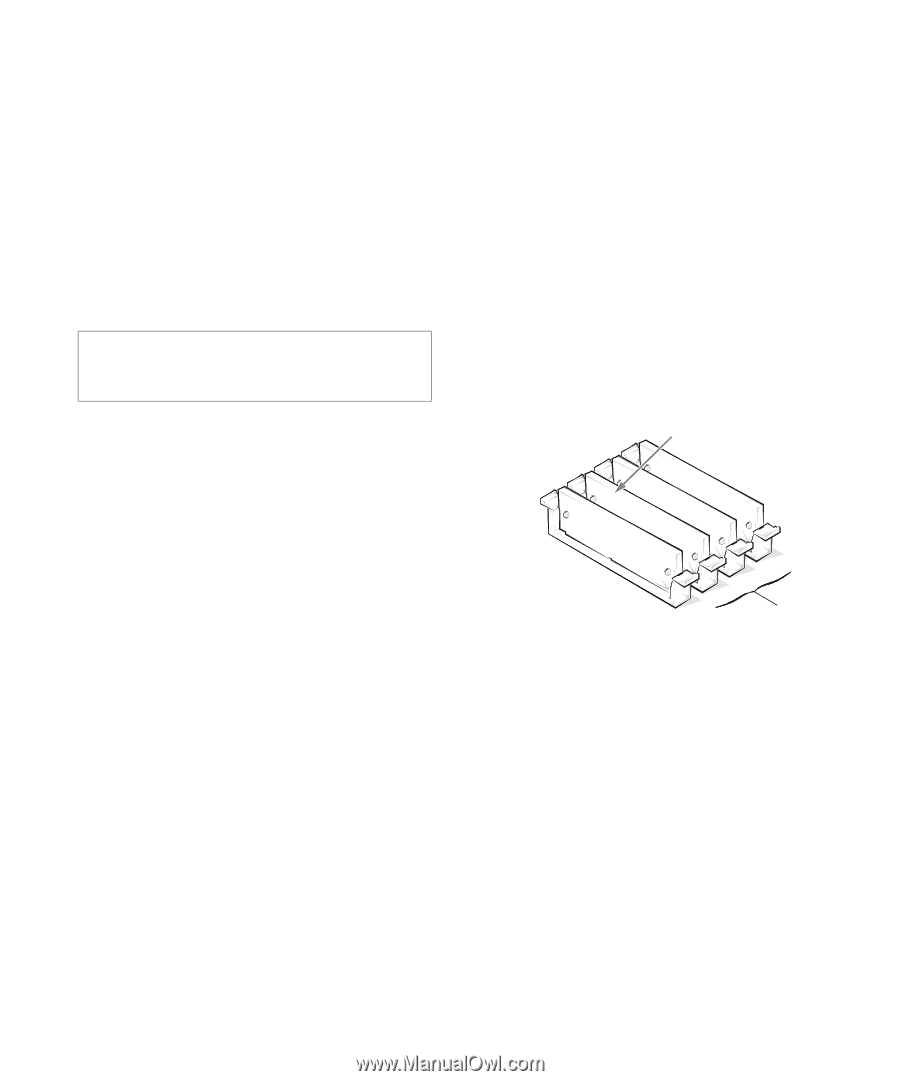
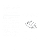
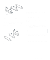
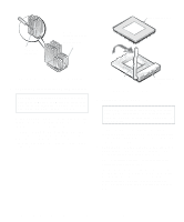
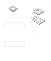
Removing an Expansion Card Follow this general procedure to remove an expansion card: 1. If you are removing an ISA expansion card, enter the ICU and remove the expansion card from your configuration. See Chapter 3, "Using the ISA Configuration Utility," for instructions. 2. Remove the computer cover according to the instructions in "Removing the Computer Cover" in Chapter 5. CAUTION: See "Protecting Against Electrostatic Discharge" in the safety instructions at the front of this guide. 3. If necessary, disconnect any cables connected to the card. 4. Remove the expansion-card cage as instructed in "Removing the Expansion-Card Cage" in Chapter 5. 5. Position the expansion-card cage so that the riser board lies horizontal on your work surface, and unscrew the mounting bracket of the card you want to remove. 6. Grasp the card by its outside corners, and ease it out of its connector. 7. If you are removing the card permanently, install a metal filler bracket over the empty card-slot opening. NOTE: Installing filler brackets over empty card-slot openings is necessary to maintain Federal Communications Commission (FCC) certification of the system. The brackets also keep dust and dirt out of your computer. 8. Replace the expansion-card cage in the chassis as instructed in "Replacing the Expansion-Card Cage" in Chapter 5. 9. Replace the computer cover, reconnect your computer and peripherals to their power sources, and turn them on. Adding Memory Memory can be increased to a maximum of 128 megabytes (MB) by installing combinations of 4-, 8-, 16-, or 32-MB extended-data out (EDO) single in-line memory modules (SIMMs) in the four SIMM sockets on the system board. Figure 6-6 shows the SIMMs and SIMM sockets. SIMMs (4) A D CB SIMM sockets Figure 6-6. SIMMs and SIMM Sockets SIMM Installation Guidelines When installing SIMMs, follow these guidelines: • SIMMs must be installed in pairs of the same capacity. • One SIMM pair must always be installed in sockets SIMM_A and SIMM_B. A second pair may be installed in sockets SIMM_C and SIMM_D. 6-4 Dell OptiPlex Gs and Gs+ Low-Profile Systems Reference and Installation Guide
-
 1
1 -
2
-
3
-
4
-
5
-
6
-
7
-
8
-
9
-
10
-
11
-
12
-
13
-
14
-
15
-
16
-
17
-
18
-
19
-
20
-
21
-
22
-
23
-
24
-
25
-
26
-
27
-
28
-
29
-
30
-
31
-
32
-
33
-
34
-
35
-
36
-
37
-
38
-
39
-
40
-
41
-
42
-
43
-
44
-
45
-
46
-
47
-
48
-
49
-
50
-
51
-
52
-
53
-
54
-
55
-
56
-
57
-
58
-
59
-
60
-
61
-
62
-
63
-
64
-
65
-
66
-
 67
67 -
 68
68 -
 69
69 -
 70
70 -
 71
71 -
 72
72 -
 73
73 -
 74
74 -
 75
75 -
 76
76 -
 77
77 -
78
-
79
-
80
-
81
-
82
-
83
-
84
-
85
-
86
-
87
-
88
-
89
-
90
-
91
-
92
-
93
-
94
-
95
-
96
-
97
-
98
-
99
-
100
-
101
-
102
-
103
-
104
-
105
-
106
-
107
-
108
-
109
-
110
-
111
-
112
-
113
-
114
-
115
-
116
-
117
-
118
-
119
-
120
-
121
 |
 |