Dell PowerEdge 2650 Information Update - Page 5
System Board Connectors for Memory Modules
 |
View all Dell PowerEdge 2650 manuals
Add to My Manuals
Save this manual to your list of manuals |
Page 5 highlights
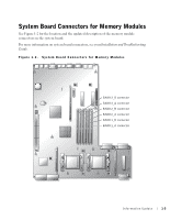
System Board Connectors for Memory Modules See Figure 1-2 for the location and the updated description of the memory module connectors on the system board. For more information on system board connectors, see your Installation and Troubleshooting Guide. Figure 1-2. System Board Connectors for Memory Modules BANK3_B connector BANK3_A connector BANK2_B connector BANK2_A connector BANK1_B connector BANK1_A connector Information Update 1-3
-
 1
1 -
 2
2 -
 3
3 -
 4
4 -
 5
5 -
 6
6 -
 7
7 -
 8
8 -
 9
9 -
 10
10 -
 11
11 -
12
-
13
-
14
-
15
-
16
-
17
-
18
-
19
-
20
-
21
-
22
-
23
-
24
-
25
-
26
-
27
-
28
-
29
-
30
-
31
-
32
-
33
-
34
-
35
-
36
-
37
-
38
-
39
-
40
-
41
-
42
-
43
-
44
-
45
-
46
-
47
-
48
-
49
-
50
-
51
-
52
-
53
-
54
-
55
-
56
-
57
-
58
 |
 |

Information Update
1-3
System Board Connectors for Memory Modules
See Figure 1-2 for the location and the updated description of the memory module
connectors on the system board.
For more information on system board connectors, see your
Installation and Troubleshooting
Guide
.
Figure 1-2.
System Board Connectors for Memory Modules
BANK1_A connector
BANK1_B connector
BANK2_A connector
BANK2_B connector
BANK3_A connector
BANK3_B connector