Dell PowerEdge 2650 Rack Installation Guide - Page 33
Installing the System in the Rack, Installing the Cable-Management Arm, Routing Cables
 |
View all Dell PowerEdge 2650 manuals
Add to My Manuals
Save this manual to your list of manuals |
Page 33 highlights
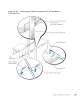
Installing the System in the Rack CAUTION: Due to the size and weight of the system, never attempt to install the system by yourself. NOTE: The procedure for installing a system into a rack is identical for flush-mount and center-mount slide assemblies. 1 Pull the slides out to their fully extended position. CAUTION: Because of the size and weight of the system, never attempt to install the system in the slide assemblies by yourself. 2 Lift the system into position (see Figure 1-17). 3 Place one hand on the front-bottom of the system and the other hand on the back- bottom of the system. 4 Tilt the back of the system down while aligning the back shoulder screws on the sides of the system with the back slots on the slide assemblies. 5 Engage the back shoulder screws into their slots. 6 Lower the front of the system, and engage the front and middle shoulder screws in their slots (the middle slot is just behind the yellow system release latch) (see Figure 1-17). When all shoulder screws are properly seated, the yellow latch on each slide assembly clicks and locks the system into the slide assembly. 7 Press up on the green slide release latch at the side of each slide to slide the system completely into the rack (see Figure 1-17). 8 Push in and turn the captive thumbscrews on each side of the front chassis panel to secure the system to the rack. NOTE: Use the yellow system release latch whenever you wish to remove the system from the slide assemblies. Installing the Cable-Management Arm See "Installing the Cable-Management Arm" in "Four-Post Rack Installation" found earlier in this document. Routing Cables See "Routing Cables" in "Four-Post Rack Installation" found earlier in this document. You have completed the installation of the rack kit in a two-post rack. Rack Installation Guide 1-27
-
 1
1 -
2
-
3
-
4
-
5
-
6
-
7
-
8
-
9
-
10
-
11
-
12
-
13
-
14
-
15
-
16
-
17
-
18
-
19
-
20
-
21
-
22
-
23
-
24
-
25
-
26
-
27
-
 28
28 -
 29
29 -
 30
30 -
 31
31 -
 32
32 -
 33
33 -
 34
34 -
 35
35 -
 36
36 -
 37
37 -
 38
38 -
39
-
40
-
41
-
42
-
43
-
44
-
45
-
46
-
47
-
48
-
49
-
50
-
51
-
52
-
53
-
54
-
55
-
56
-
57
-
58
-
59
-
60
-
61
-
62
-
63
-
64
-
65
-
66
-
67
-
68
-
69
-
70
-
71
-
72
-
73
-
74
-
75
-
76
-
77
-
78
-
79
-
80
-
81
-
82
-
83
-
84
-
85
-
86
-
87
-
88
-
89
-
90
-
91
-
92
-
93
-
94
-
95
-
96
-
97
-
98
-
99
-
100
-
101
-
102
-
103
-
104
-
105
-
106
-
107
-
108
-
109
-
110
-
111
-
112
-
113
-
114
-
115
-
116
-
117
-
118
-
119
-
120
-
121
-
122
-
123
-
124
-
125
-
126
-
127
-
128
-
129
-
130
-
131
-
132
-
133
-
134
-
135
-
136
-
137
-
138
-
139
-
140
-
141
-
142
-
143
-
144
-
145
-
146
-
147
-
148
-
149
-
150
-
151
-
152
-
153
-
154
-
155
-
156
-
157
-
158
-
159
-
160
-
161
-
162
-
163
-
164
-
165
-
166
-
167
-
168
-
169
-
170
-
171
-
172
-
173
-
174
-
175
-
176
-
177
-
178
-
179
-
180
-
181
-
182
-
183
-
184
 |
 |
