Dell PowerEdge 2950 Rack Installation Guide - Page 9
Rack Stabilizer Feet, Recommended Tools and Supplies, Rack Kit Contents - cable management
 |
View all Dell PowerEdge 2950 manuals
Add to My Manuals
Save this manual to your list of manuals |
Page 9 highlights
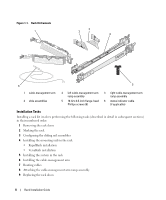
Rack Stabilizer Feet CAUTION: Before installing systems in a rack, install front and side stabilizers on stand-alone racks or the front stabilizer on racks joined to other racks. Failure to install stabilizers accordingly before installing systems in a rack could cause the rack to tip over, potentially resulting in bodily injury under certain circumstances. Therefore, always install the stabilizer(s) before installing components in the rack. The stabilizer feet help prevent the rack from tipping over. See the documentation provided with the rack cabinet for instructions on installing and anchoring the stabilizer feet. Recommended Tools and Supplies You may need the following items to install the system in a four-post rack cabinet: • #2 Phillips screwdriver • Masking tape or a felt-tip pen, for use in marking the mounting holes to be used Rack Kit Contents • One pair of slide assemblies • One cable-management arm • One left cable-management arm ramp assembly • One right cable-management arm ramp assembly • One status indicator cable (if applicable) • Eight 10-32 x 0.5-inch flange-head Phillips screws NOTE: The nonmetric screws described in illustrations and in procedural steps are identified by size and number of threads per inch. For example, a #10 Phillips-head screw with 32 threads per inch is identified as a 10-32 screw. NOTE: Both the right and left cable-management arm ramp assemblies are illustrated in Figure 1-1. Depending on the orientation of the cable-management arm (CMA), you will only use one ramp assembly to secure the CMA to the back of the rack. For more information, see "Attaching the Cable-Management Arm Ramp Assembly" on page 19. Rack Installation Guide 7
-
 1
1 -
2
-
3
-
 4
4 -
 5
5 -
 6
6 -
 7
7 -
 8
8 -
 9
9 -
 10
10 -
 11
11 -
 12
12 -
 13
13 -
 14
14 -
15
-
16
-
17
-
18
-
19
-
20
-
21
-
22
-
23
-
24
-
25
-
26
-
27
-
28
-
29
-
30
-
31
-
32
-
33
-
34
-
35
-
36
-
37
-
38
-
39
-
40
-
41
-
42
-
43
-
44
-
45
-
46
-
47
-
48
-
49
-
50
-
51
-
52
-
53
-
54
-
55
-
56
-
57
-
58
-
59
-
60
-
61
-
62
-
63
-
64
-
65
-
66
-
67
-
68
-
69
-
70
-
71
-
72
-
73
-
74
-
75
-
76
-
77
-
78
-
79
-
80
-
81
-
82
-
83
-
84
-
85
-
86
-
87
-
88
-
89
-
90
-
91
-
92
-
93
-
94
-
95
-
96
-
97
-
98
-
99
-
100
-
101
-
102
-
103
-
104
-
105
-
106
-
107
-
108
-
109
-
110
-
111
-
112
 |
 |
