Dell PowerEdge 2970 Rack Installation Guide - Page 21
Attaching the Cable-Management Arm Ramp Assembly, stretch
 |
View all Dell PowerEdge 2970 manuals
Add to My Manuals
Save this manual to your list of manuals |
Page 21 highlights
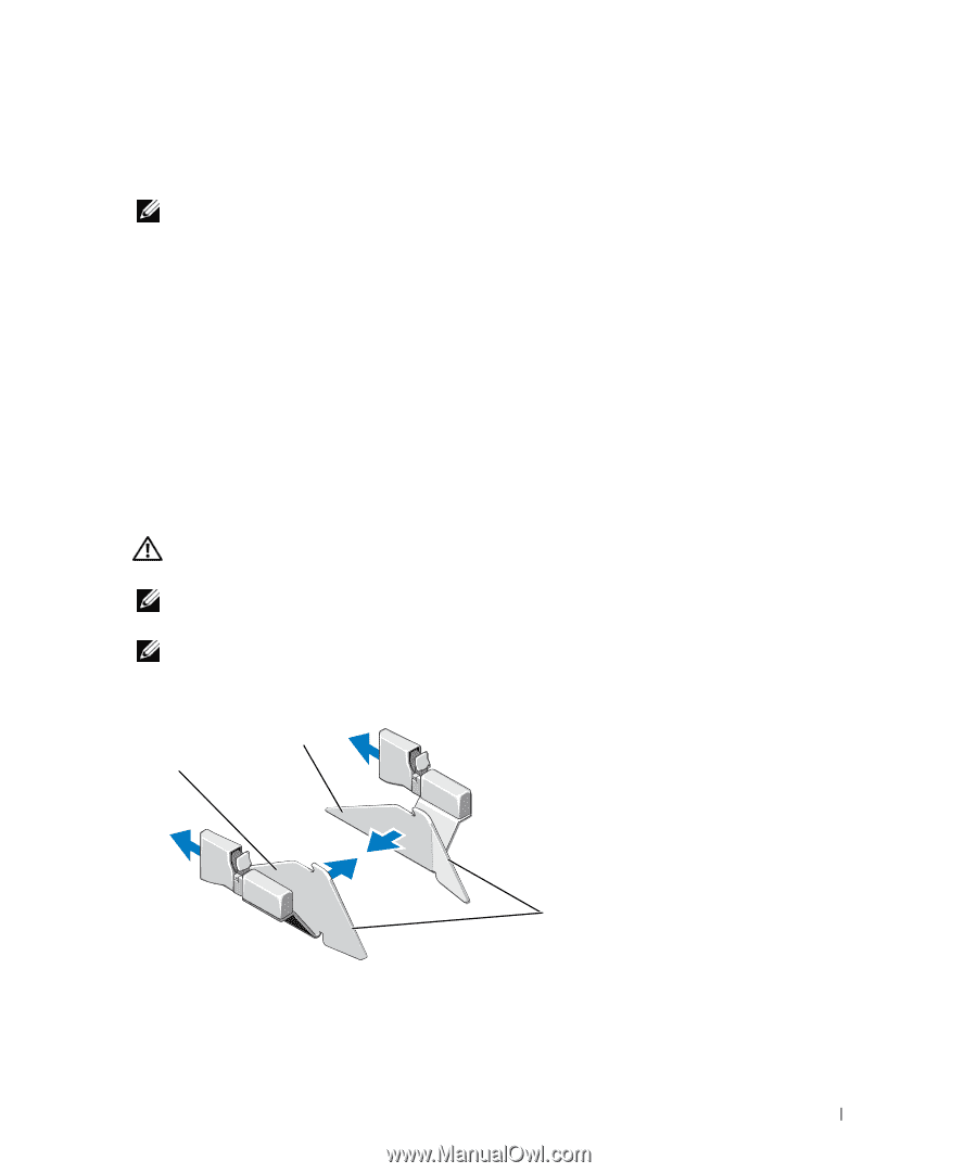
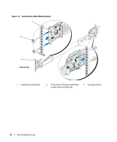
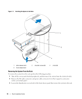
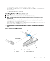
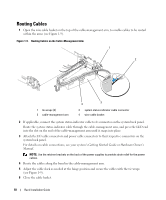
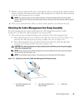
7 Slide the system in and out of the rack to verify that the cables are routed correctly and do not bind, stretch, or interfere with the movement of the cable-management arm. Adjust the cable positioning inside the cable-management arm as needed. NOTE: If you pull the system out to its furthest extension, the slide assemblies will lock in the extended position. To release the lock, press the slide release latch on the side of each slide and then slide the system into the rack. 8 When you are satisfied that the cables are routed correctly, push the system fully into the rack. Attaching the Cable-Management Arm Ramp Assembly The cable-management arm ramp assembly guides the cable-management arm into a stable, level position. To attach the cable-management arm ramp assembly: 1 Select only one ramp assembly, depending on the orientation of the cable-management arm. a If the cable-management arm is attached on the right side of the rack (as shown in Figure 1-11), attach the left cable-management arm ramp assembly to the rack (see Figure 1-10). b If the cable-management arm is attached on the left side of the rack, attach the right cablemanagement arm ramp assembly to the rack (see Figure 1-10). CAUTION: The cable-management arm ramp assembly must be installed to prevent long-term sagging of the cable-management arm. NOTE: Ensure that you use the cable-management arm ramp assembly with the metal ramp facing toward the center of the rack (see Figure 1-10). NOTE: The orientation shown in Figure 1-10 presumes you are facing the back of the system. Figure 1-10. Orientation for the Left or Right Cable-Management Arm Ramp Assembly 2 1 3 1 left cable-management arm ramp assembly 2 right cable-management arm ramp assembly 3 metal ramp Rack Installation Guide 19
-
 1
1 -
2
-
3
-
4
-
5
-
6
-
7
-
8
-
9
-
10
-
11
-
12
-
13
-
14
-
15
-
 16
16 -
 17
17 -
 18
18 -
 19
19 -
 20
20 -
 21
21 -
 22
22 -
 23
23 -
 24
24 -
 25
25 -
 26
26 -
27
-
28
-
29
-
30
-
31
-
32
-
33
-
34
-
35
-
36
-
37
-
38
-
39
-
40
-
41
-
42
-
43
-
44
-
45
-
46
-
47
-
48
-
49
-
50
-
51
-
52
-
53
-
54
-
55
-
56
-
57
-
58
-
59
-
60
-
61
-
62
-
63
-
64
-
65
-
66
-
67
-
68
-
69
-
70
-
71
-
72
-
73
-
74
-
75
-
76
-
77
-
78
-
79
-
80
-
81
-
82
-
83
-
84
-
85
-
86
-
87
-
88
-
89
-
90
-
91
-
92
-
93
-
94
-
95
-
96
-
97
-
98
-
99
-
100
-
101
-
102
-
103
-
104
-
105
-
106
-
107
-
108
-
109
-
110
-
111
-
112
 |
 |