Dell PowerEdge PDU Metered LCD Cabling PowerEdge T620 - Page 5
Routing the power cables through the strain reliefs, Installing the CMA
 |
View all Dell PowerEdge PDU Metered LCD manuals
Add to My Manuals
Save this manual to your list of manuals |
Page 5 highlights
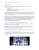
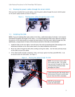
Cable Routing Procedures for Dell PowerEdge T620 Systems 1.2. Routing the power cables through the strain reliefs After you have installed the tray and cables, route the power cables through the strain reliefs located on the power supply handles as shown in Figure 2. Figure 2. Routing power cables through the strain reliefs 1.3. Installing the CMA NOTE: If you are installing fiber-optic cables in the CMA, a cable bend radius of at least 1 inch must be maintained throughout the length of the cable. It is recommended that fiber-optic cables be routed on the exterior of the cable bundle to increase the bend radius of the fiber-optic cables through the CMA. Additionally, a large amount of slack at the entrance and exit of the CMA is recommended. 1. Install the CMA on the rear right or rear left side of the rails by attaching both CMA housings to the attachment brackets on the rails as described in the CMA Installation Instructions. 2. Route the cables through the CMA while avoiding twisting the cables. Use the hook-and-loop straps on the CMA to secure the cables. 3. If the cable bundle includes a keyboard, video, and mouse system interface pod (KVM SIP), it can be placed inside the CMA basket. See Figure 3. Figure 3. Routing the cables through the CMA NOTE: Do not store excess cable slack inside the CMA. The cables may protrude through the CMA, thus causing binding and potentially damaging the cables. Cables entering the CMA should have a small amount of slack to avoid cable strain when the CMA is extended. KVM SIP can be placed inside the CMA basket. 5
-
 1
1 -
 2
2 -
 3
3 -
 4
4 -
 5
5 -
 6
6 -
 7
7
 |
 |
