Dell PowerEdge R910 Information Update - Page 7
Hardware Owner's Manual Updates - bios
 |
View all Dell PowerEdge R910 manuals
Add to My Manuals
Save this manual to your list of manuals |
Page 7 highlights
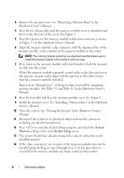
Hardware Owner's Manual Updates BIOS Setup Options Default Settings Update Table 2. Default Settings for BIOS Setup Options Screen Memory Settings Power Management Integrated Devices SATA Settings Option System Memory Testing Power Management SR-IOV Global Enable Embedded SATA Default Option Disabled Active Power Controller Disabled ATA Mode Power Supply Redundancy Mode (With a 10 Gb I/O Card) For a redundant system configuration with a 10 Gb I/O card and four power supplies, the redundancy mode is 2+1. System Memory Follow the procedure given below for installing and removing the memory modules if your system has a memory riser as shown in Figure 1. Installing Memory Modules WARNING: The memory modules are hot to the touch for some time after the system has been powered down. Allow time for the memory modules to cool before handling them. Handle the memory modules by the card edges and avoid touching the components on the memory module. CAUTION: Many repairs may only be done by a certified service technician. You should only perform troubleshooting and simple repairs as authorized in your product documentation, or as directed by the online or telephone service and support team. Damage due to servicing that is not authorized by Dell is not covered by your warranty. Read and follow the safety instructions that came with the product. 1 Turn off the system, including any attached peripherals, and disconnect the system from the electrical outlet. 2 Open the system. See "Opening the System" in the Hardware Owner's Manual. Information Update 7
-
 1
1 -
 2
2 -
 3
3 -
 4
4 -
 5
5 -
 6
6 -
 7
7 -
 8
8 -
 9
9 -
 10
10 -
 11
11 -
 12
12 -
13
-
14
-
15
-
16
-
17
-
18
-
19
-
20
-
21
-
22
-
23
-
24
-
25
-
26
-
27
-
28
-
29
-
30
-
31
-
32
-
33
-
34
-
35
-
36
-
37
-
38
-
39
-
40
-
41
-
42
-
43
-
44
-
45
-
46
-
47
-
48
-
49
-
50
-
51
-
52
-
53
-
54
-
55
-
56
-
57
-
58
-
59
-
60
-
61
-
62
-
63
-
64
-
65
-
66
-
67
-
68
-
69
-
70
-
71
-
72
-
73
-
74
-
75
-
76
-
77
-
78
-
79
-
80
-
81
-
82
-
83
-
84
-
85
-
86
-
87
-
88
 |
 |