Dell Studio XPS M1340 Service Manual
Dell Studio XPS M1340 Manual
 |
View all Dell Studio XPS M1340 manuals
Add to My Manuals
Save this manual to your list of manuals |
Dell Studio XPS M1340 manual content summary:
- Dell Studio XPS M1340 | Service Manual - Page 1
Dell™ Studio XPS™ 1340 Service Manual Before You Begin Base Cover Coin-Cell Battery Hard Drive Memory Rear Caps Processor Heat Sink Processor Wireless Mini-Card Palm Rest Keyboard Display Assembly Optical Drive Status Light Board System Board eSATA Connector AC Adapter Connector Battery Latch - Dell Studio XPS M1340 | Service Manual - Page 2
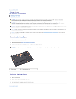
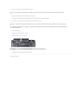
to Contents Page Base Cover Dell™ Studio XPS™ 1340 Service Manual Removing the Base Cover Replacing support personnel. 1 base cover 2 captive screws (10) Replacing the Base Cover 1. Replace the base cover. 2. Tighten the ten captive screws on the base cover. 3. Slide the battery into the battery - Dell Studio XPS M1340 | Service Manual - Page 3
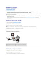
Back to Contents Page Battery Latch Assembly Dell™ Studio XPS™ 1340 Service Manual Removing the Battery Latch Assembly Replacing the Battery Latch Assembly CAUTION: Before working inside your computer, read the safety information that shipped with your computer. For additional safety best practices - Dell Studio XPS M1340 | Service Manual - Page 4
4. Replace the mylar tapes. Ensure that the newly installed latch moves smoothly and freely when pushed and released. 5. Follow the instructions in Replacing the System Board. NOTICE: Before turning on the computer, replace all screws and ensure that no stray screws remain inside the computer. - Dell Studio XPS M1340 | Service Manual - Page 5
Dell™ Studio XPS™ 1340 Service Manual BIOS ® Windows Vista 10 card. Hold a card by its edges. Hold a component such as a processor by its edges, not by its pins. NOTICE: Only a certified service technician should perform repairs on your computer. Damage due to servicing that is not authorized by Dell - Dell Studio XPS M1340 | Service Manual - Page 6
the ExpressCard slot and the 8-in--1 Memory Card Reader. 5. Disconnect your computer and all attached devices from their electrical outlets. NOTICE: To help prevent damage to the system board, you must remove the battery from the battery bay before you service the computer. NOTICE: To avoid damage - Dell Studio XPS M1340 | Service Manual - Page 7
to Contents Page Flashing the BIOS Dell™ Studio XPS™ 1340 Service Manual Flashing the BIOS From a CD Flashing the BIOS From the Hard Drive If a BIOS upgrade CD is provided with the new system board, flash the BIOS from the CD. If you do not have a BIOS upgrade CD, flash the BIOS from the hard drive - Dell Studio XPS M1340 | Service Manual - Page 8
- Dell Studio XPS M1340 | Service Manual - Page 9
Page Coin-Cell Battery Dell™ Studio XPS™ 1340 Service Manual Removing the Coin-Cell Battery Replacing the Coin-Cell Battery CAUTION: Before Cell Battery 1. Follow the instructions in Before You Begin. 2. Remove the base cover (see Removing the Base Cover). 3. Disconnect the coin-cell battery cable - Dell Studio XPS M1340 | Service Manual - Page 10
Back to Contents Page Processor Dell™ Studio XPS™ 1340 Service Manual Removing the Processor Installing the Processor CAUTION: Before working inside your computer, read the safety information that shipped with your computer. For additional safety best - Dell Studio XPS M1340 | Service Manual - Page 11
Processor Heat Sink). 5. Replace the rear caps (see Replacing the Rear Caps). 6. Replace the base cover (see Replacing the Base Cover). 7. Slide the battery into the battery bay until it clicks into place. 8. Update the BIOS using the BIOS upgrade CD. See (Flashing the BIOS). Back to Contents Page - Dell Studio XPS M1340 | Service Manual - Page 12
Back to Contents Page Processor Heat Sink Dell™ Studio XPS™ 1340 Service Manual Central Processor Heat Sink Graphic Processor Heat Sink/Thermal Fan CAUTION: Before working inside your computer, read the safety information that shipped with your computer. - Dell Studio XPS M1340 | Service Manual - Page 13
base cover (see Replacing the Base Cover). 6. Slide the battery into the battery bay until it clicks into place. Graphic Processor Heat Sink/Thermal thermal fan may differ according to your system configuration. 1. Follow the instructions in Before You Begin. 2. Remove the base cover (see Removing - Dell Studio XPS M1340 | Service Manual - Page 14
the Central Processor Heat Sink) 6. Replace the rear caps (see Replacing the Rear Caps). 7. Replace the base cover (see Replacing the Base Cover). 8. Slide the battery into the battery bay until it clicks into place. Back to Contents Page - Dell Studio XPS M1340 | Service Manual - Page 15
Back to Contents Page Display Assembly Dell™ Studio XPS™ 1340 Service Manual Removing the Display Assembly Replacing the Display Assembly CAUTION: Before working inside your computer, read the safety information that shipped with your computer. For additional - Dell Studio XPS M1340 | Service Manual - Page 16
routing guides. 9. Remove the four screws (two on either side) that secure the display assembly to the computer base. 10. Lift Card antenna cables through the system board and into their routing guides. 4. Reconnect the Mini-Card cables to the Mini-Card, if applicable (see Replacing the Mini-Card - Dell Studio XPS M1340 | Service Manual - Page 17
Back to Contents Page eSATA Connector Dell™ Studio XPS™ 1340 Service Manual Removing the eSATA Connector Replacing the eSATA Connector CAUTION: Before working inside your computer, read the safety information that shipped with your computer. For additional - Dell Studio XPS M1340 | Service Manual - Page 18
NOTICE: Before turning on the computer, replace all screws and ensure that no stray screws remain inside the computer. Failure to do so may result in damage to the computer. 5. Replace the system board (see Replacing the System Board). 6. Replace the display assembly (see Replacing the Display - Dell Studio XPS M1340 | Service Manual - Page 19
Back to Contents Page Hard Drive Dell™ Studio XPS™ 1340 Service Manual Removing the Hard Drive Replacing the Hard Drive CAUTION: If you remove the hard drive from the computer when the drive is hot, do not - Dell Studio XPS M1340 | Service Manual - Page 20
damage to the computer. 7. Slide the battery into the battery bay until it clicks into place. 8. Install the operating system for your computer, as needed (see Dell Technology Guide). 9. Install the drivers and utilities for your computer, as needed (see Dell Technology Guide). Back to Contents Page - Dell Studio XPS M1340 | Service Manual - Page 21
Back to Contents Page Rear Caps Dell™ Studio XPS™ 1340 Service Manual Removing the Rear Caps Replacing the Rear Caps CAUTION: Before working inside your computer, read the safety information that shipped with your computer. For additional - Dell Studio XPS M1340 | Service Manual - Page 22
Back to Contents Page Keyboard Dell™ Studio XPS™ 1340 Service Manual Removing the Keyboard Replacing the Keyboard CAUTION: Before working inside your computer, read the safety information that shipped with your computer. For additional safety best - Dell Studio XPS M1340 | Service Manual - Page 23
3 keyboard shield 4 screws (10) 5 keyboard 6 dual multimedia board/power board cable connector 7 backlit keyboard cable connector (availability varies according to region) Replacing the Keyboard 1. Replace the keyboard on the - Dell Studio XPS M1340 | Service Manual - Page 24
Back to Contents Page Status Light Board Dell™ Studio XPS™ 1340 Service Manual Removing the Status Light Board Replacing the Status Light Board CAUTION: Before working inside your computer, read the safety information that shipped with your computer. - Dell Studio XPS M1340 | Service Manual - Page 25
- Dell Studio XPS M1340 | Service Manual - Page 26
Back to Contents Page Memory Dell™ Studio XPS™ 1340 Service Manual Removing the Memory Module(s) Replacing the Memory Module(s) CAUTION: Before working inside your computer, read the safety information that shipped with your computer. For additional safety best practices information, see the - Dell Studio XPS M1340 | Service Manual - Page 27
base cover (see Replacing the Base Cover). 4. Slide the battery into the battery bay, or connect the AC adapter to your computer and memory and automatically updates the system configuration information. To confirm the amount of memory installed in the computer, click Start ® Help and Support® Dell - Dell Studio XPS M1340 | Service Manual - Page 28
Back to Contents Page Wireless Mini-Card Dell™ Studio XPS™ 1340 Service Manual Removing the Mini-Card Replacing the Mini-Card CAUTION: Before working inside your computer, read the safety information that shipped with your computer. For additional safety best practices information, see the - Dell Studio XPS M1340 | Service Manual - Page 29
Cover). 8. Slide the battery into the battery bay until it clicks into place. 9. Install the drivers and utilities for your computer, as required. For more information, see the Dell Technology Guide. NOTE: If you are installing a communication card from a source other than Dell, you must install the - Dell Studio XPS M1340 | Service Manual - Page 30
Back to Contents Page - Dell Studio XPS M1340 | Service Manual - Page 31
Back to Contents Page Optical Drive Dell™ Studio XPS™ 1340 Service Manual Removing the Optical Drive Replacing the Optical Drive CAUTION: Before working inside your computer, read the safety information that shipped with your computer. For additional - Dell Studio XPS M1340 | Service Manual - Page 32
6. Detach the interposer from the optical drive. Replacing the Optical Drive 1. Attach the interposer to the optical drive. 2. Place the optical drive in the computer base. 3. Replace the two screws that secure the optical drive to the system board. 4. Turn the computer over and replace the screw - Dell Studio XPS M1340 | Service Manual - Page 33
Back to Contents Page Palm Rest Dell™ Studio XPS™ 1340 Service Manual Removing the Palm Rest Replacing the Palm Rest CAUTION: Before working inside your computer, read the safety information that shipped with your computer. For additional - Dell Studio XPS M1340 | Service Manual - Page 34
screws in the computer base. 4. Replace the rear caps (see Replacing the Rear Caps). 5. Replace the base cover (see Replacing the Base Cover). 6. Slide the battery into the battery bay until it clicks into place. Back to Contents Page - Dell Studio XPS M1340 | Service Manual - Page 35
Page AC Adapter Connector Dell™ Studio XPS™ 1340 Service Manual Removing the AC Adapter instructions in Before You Begin. 2. Remove the eSATA connector (see Removing the eSATA Connector). 3. Remove the screw that secures the AC adapter connector. 4. Remove the AC adapter cable from the routing guide - Dell Studio XPS M1340 | Service Manual - Page 36
4. Replace the eSATA connector (see Replacing the eSATA Connector). Back to Contents Page - Dell Studio XPS M1340 | Service Manual - Page 37
System Board Dell™ Studio XPS™ 1340 Service Manual Removing the instructions in Before You Begin. 2. Remove the base cover (see Removing the Base Cover). 3. Remove the coin-cell battery (see Removing the Coin-Cell Battery). 4. Remove the hard drive (see Removing the Hard Drive). 5. Remove the memory - Dell Studio XPS M1340 | Service Manual - Page 38
achieved. 10. Replace the processor heat sinks (see Replacing the Central Processor Heat Sink and Replacing the Graphic Processor Heat Sink/Thermal Fan). 11. Replace the rear caps (see Replacing the Rear Caps). 12. Replace the memory modules, if any (see Replacing the Memory Module(s)). 13. Replace - Dell Studio XPS M1340 | Service Manual - Page 39
14. Replace the coin-cell battery (see Replacing the Coin-Cell Battery). 15. Replace the base cover (see Service Tag into the BIOS of the replacement system board. 17. Insert the BIOS upgrade CD that accompanied the replacement system board into the appropriate drive. Follow the instructions
-
 1
1 -
 2
2 -
 3
3 -
 4
4 -
 5
5 -
 6
6 -
 7
7 -
8
-
9
-
10
-
11
-
12
-
13
-
14
-
15
-
16
-
17
-
18
-
19
-
20
-
21
-
22
-
23
-
24
-
25
-
26
-
27
-
28
-
29
-
30
-
31
-
32
-
33
-
34
-
35
-
36
-
37
-
38
-
39
 |
 |
Dell™ Studio XPS™ 1340 Service Manual
Notes, Notices, and Cautions
Information in this document is subject to change without notice.
© 2008 Dell Inc. All rights reserved.
Reproduction of these materials in any manner whatsoever without the written permission of Dell Inc. is strictly forbidden.
Trademarks used in this text:
Dell
,
XPS
, and the
DELL
logo are trademarks of Dell Inc.;
Bluetooth
is a registered trademark owned by Bluetooth SIG, Inc. and is used by Dell under
license.
Microsoft
,
Windows
,
Windows Vista
,
and
Windows Vista start button logo
are either trademarks or registered trademarks of Microsoft Corporation in the United States and/or
other countries.
Other trademarks and trade names may be used in this document to refer to either the entities claiming the marks and names or their products. Dell Inc. disclaims any
proprietary interest in trademarks and trade names other than its own.
Model PP17S
December 2008 Rev. A00
Before You Begin
Base Cover
Coin
-
Cell Battery
Hard Drive
Memory
Rear Caps
Processor Heat Sink
Processor
Wireless Mini
-
Card
Palm Rest
Keyboard
Display Assembly
Optical Drive
Status Light Board
System Board
eSATA Connector
AC Adapter Connector
Battery Latch Assembly
Flashing the BIOS
NOTE:
A NOTE indicates important information that helps you make better use of your computer.
NOTICE:
A NOTICE indicates either potential damage to hardware or loss of data and tells you how to avoid the problem.
CAUTION:
A CAUTION indicates a potential for property damage, personal injury, or death.