Dell Vostro 20 All-in-One 3052 Dell Vostro 203052 Owners Manual
Dell Vostro 20 All-in-One 3052 Manual
 |
View all Dell Vostro 20 All-in-One 3052 manuals
Add to My Manuals
Save this manual to your list of manuals |
Dell Vostro 20 All-in-One 3052 manual content summary:
- Dell Vostro 20 All-in-One 3052 | Dell Vostro 203052 Owners Manual - Page 1
Dell Vostro 20-3052 Owner's Manual Regulatory Model: W15B Regulatory Type: W15B002 - Dell Vostro 20 All-in-One 3052 | Dell Vostro 203052 Owners Manual - Page 2
potential damage to hardware or loss of data and tells you how to avoid the problem. WARNING: A WARNING indicates a potential for property damage, personal injury, or death. Copyright © 2015 Dell Inc. All rights reserved. This product is protected by U.S. and international copyright and intellectual - Dell Vostro 20 All-in-One 3052 | Dell Vostro 203052 Owners Manual - Page 3
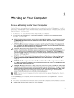
all power sources troubleshooting and simple repairs as authorized in your product documentation, or as directed by the online or telephone service and support team. Damage due to servicing that is not authorized by Dell is not covered by your warranty. Read and follow the safety instructions - Dell Vostro 20 All-in-One 3052 | Dell Vostro 203052 Owners Manual - Page 4
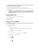
Press and hold the power button while the computer before you turn off your computer. 1. Shut down the operating system: • In Windows 8: - Settings. b. Select the - Using a mouse: and then select Shut down a. Point to upper-right corner of the screen and click Settings. b. Click the • In Windows - Dell Vostro 20 All-in-One 3052 | Dell Vostro 203052 Owners Manual - Page 5
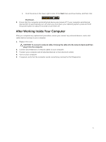
down your operating system, press and hold the power button for about 6 seconds to turn them off. After Working Inside Your Computer After you complete any replacement procedure, ensure you connect any external devices, cards, and cables before turning on your computer. 1. Replace the cover. CAUTION - Dell Vostro 20 All-in-One 3052 | Dell Vostro 203052 Owners Manual - Page 6
2 Removing and Installing Components This section provides detailed information on how to remove or install the components from your computer. Removing the Stand 1. Follow the procedures in Before Working Inside Your Computer. 2. Place the computer on a flat surface, display facing downwards. 3. Pry - Dell Vostro 20 All-in-One 3052 | Dell Vostro 203052 Owners Manual - Page 7
5. Remove the stand from the computer. Installing the Stand 1. Align the stand on the computer, and tighten the screws to secure the stand to the computer. 2. Place and press the hinge cover on the computer until it clicks into place. 3. Follow the procedures in After Working Inside Your Computer. - Dell Vostro 20 All-in-One 3052 | Dell Vostro 203052 Owners Manual - Page 8
3. Perform the following steps as shown in the illustration: a. Press on the tab indicated using a scribe [1]. b. Slide the optical-disk drive (ODD) out of the computer [2]. 4. Remove the screws that secure the optical-disk drive bracket, and remove it from the optical drive [1,2]. Installing the - Dell Vostro 20 All-in-One 3052 | Dell Vostro 203052 Owners Manual - Page 9
Removing the Back Cover 1. Follow the procedures in Before Working Inside Your Computer. 2. Remove: a. stand b. optical-disk drive 3. Perform the following steps as shown in the illustration: a. Pry the edge of the base cover [1]. b. Remove the back cover from the computer [2]. Installing the Back - Dell Vostro 20 All-in-One 3052 | Dell Vostro 203052 Owners Manual - Page 10
4. Remove the hard-drive from the computer. 5. Remove the screws that secure the hard-drive to the bracket, lift the hard-drive from bracket [1,2] 10 - Dell Vostro 20 All-in-One 3052 | Dell Vostro 203052 Owners Manual - Page 11
-drive cable. 6. Install: a. back cover b. optical-disk drive c. stand 7. Follow the procedures in After Working Inside Your Computer. Removing the Power-Switch Board 1. Follow the procedures in Before Working Inside Your Computer. 2. Remove: a. stand b. optical-disk drive c. back cover 3. Perform - Dell Vostro 20 All-in-One 3052 | Dell Vostro 203052 Owners Manual - Page 12
-Switch Board 1. Connect the power-switch cable to the power-switch board. Insert the power-switch board into its slot on the computer. 2. Install: a. back cover b. optical-disk drive c. stand 3. Follow the procedures in After Working Inside Your Computer. Removing - Dell Vostro 20 All-in-One 3052 | Dell Vostro 203052 Owners Manual - Page 13
the computer. 2. Install: a. back cover b. optical-disk drive c. stand 3. Follow the procedures in After Working Inside Your Computer. Removing the Memory 1. Follow the procedures in Before Working Inside Your Computer. 2. Remove: a. stand b. optical-disk drive c. back cover d. system-board shield - Dell Vostro 20 All-in-One 3052 | Dell Vostro 203052 Owners Manual - Page 14
NOTE: Please use DIMM 2 slot if there is only one memory module available. 1. Align the notch on the memory-card with the tab on the system-board connector. 2. Press down on the memory module until the release tabs spring back to secure them in place. 3. Install: a. system-board shield b. back - Dell Vostro 20 All-in-One 3052 | Dell Vostro 203052 Owners Manual - Page 15
Installing the System Fan 1. Align the system fan with the heatsink such that pins of the bracket are in line with the holes of the system fan and tighten the screws to secure it to the computer. 2. Connect the system-fan cable to the system board. 3. Install: a. system-board shield b. back cover c. - Dell Vostro 20 All-in-One 3052 | Dell Vostro 203052 Owners Manual - Page 16
4. Remove the heatsink assembly from the system board. Installing the Heatsink Assembly 1. Install the heatsink assembly and tighten the screws to secure it to the system board. 2. Install: a. system-board shield b. back cover c. optical-disk drive d. stand 3. Follow the procedures in After Working - Dell Vostro 20 All-in-One 3052 | Dell Vostro 203052 Owners Manual - Page 17
cover d. system-board shield 3. Perform the following steps as shown in the illustration: a. Remove the screw that secures the WLAN card and slide to remove the WLAN holder from the system board [1,2]. b. Remove the two connectors that secure the WLAN card to the system board [3]. c. Remove the WLAN - Dell Vostro 20 All-in-One 3052 | Dell Vostro 203052 Owners Manual - Page 18
Installing the WLAN Card 1. Insert the WLAN card into its slot. 2. Connect the two connectors (black cable to the black triangle and white cable to the white triangle). 3. Place the WLAN holder and tightened the screw that secures the WLAN card to the system board. 4. Install: a. stand b. optical- - Dell Vostro 20 All-in-One 3052 | Dell Vostro 203052 Owners Manual - Page 19
4. Remove the speaker from the computer. Installing the Speakers 1. Align the speakers on the computer. 2. Align the speaker cables through their tabs on the computer and connect the speaker cable to the system board. 3. Install: a. system-board shield b. back cover c. optical-disk drive d. stand 4. - Dell Vostro 20 All-in-One 3052 | Dell Vostro 203052 Owners Manual - Page 20
23. Reserved 25. AMD GPU Mars_LE 27. Memory socket 29. HDD Power connector 2. WLAN connector 4. Webcam connector 6. Password header 8. SD Card connector 10. USB 3.0 port 12. SIO IC 14. Coin Cell Battery 16. Rear USB 2.0 Port 18. DC IN connector 20. Power switch connector 22. Audio Jack connector 24 - Dell Vostro 20 All-in-One 3052 | Dell Vostro 203052 Owners Manual - Page 21
d. system-board shield e. heatsink f. WLAN card g. memory (optional) 3. Disconnect the following from the system board [1,2,3]: a. display assembly cable b. system-fan cable c. hard-drive cable d. hard-drive/optical-drive power cable e. power - Dell Vostro 20 All-in-One 3052 | Dell Vostro 203052 Owners Manual - Page 22
display assembly cable c. system fan cable d. hard-drive cable e. hard-drive/optical-drive power cable f. power-switch cable g. speaker cable h. convertor cable 4. Install: a. memory (optional) b. WLAN card c. heatsink d. system-board shield e. back cover f. optical-disk drive g. stand 5. Follow the - Dell Vostro 20 All-in-One 3052 | Dell Vostro 203052 Owners Manual - Page 23
speakers g. heatsink h. system fan i. memory j. WLAN card k. system board 3. Perform the following steps as shown in the illustration: a. Disconnect convertor cable [1]. b. Unroute the cable [2]. 4. Perform the following steps as shown in the illustration: a. Peel the power cable tape that secures - Dell Vostro 20 All-in-One 3052 | Dell Vostro 203052 Owners Manual - Page 24
5. Remove the screws that secure the display bracket to the computer. Lift the display bracket. 6. Pry the edges of the display assembly from the computer. 7. Remove the display assembly from the computer. 24 - Dell Vostro 20 All-in-One 3052 | Dell Vostro 203052 Owners Manual - Page 25
bracket to the computer. 3. Align the display assembly cable through the tabs on the display bracket. 4. Install: a. system board b. memory c. WLAN card d. system fan e. heatsink f. speakers g. system-board shield h. hard drive i. optical-disk drive j. back cover k. stand 5. Follow the procedures in - Dell Vostro 20 All-in-One 3052 | Dell Vostro 203052 Owners Manual - Page 26
BIOS‐level options. From the System Setup, you can: • Change the NVRAM settings after you add or remove hardware • View the system hardware configuration • Enable or disable integrated devices • Set performance and power management thresholds • Manage your computer security Boot Sequence Boot - Dell Vostro 20 All-in-One 3052 | Dell Vostro 203052 Owners Manual - Page 27
Main tab lists out the primary hardware features of the computer. The table below defines the function of each option. System Time System Date BIOS Version Product Name Service Tag Asset Tag CPU Type CPU Speed CPU ID Resets the time on the computer's internal clock. Resets the date on the computer - Dell Vostro 20 All-in-One 3052 | Dell Vostro 203052 Owners Manual - Page 28
ID and capacity. Displays the type of ODD. Displays the power adapter type. Displays the memory capacity and type. Displays the extended memory capacity Displays the memory speed. Advanced The Advanced tab allows you to set various functions that affect the performance of the computer. The table - Dell Vostro 20 All-in-One 3052 | Dell Vostro 203052 Owners Manual - Page 29
Camera Internal Bluetooth Internal WLAN Media Card Reader Optical Device Boot Disable USB Configuration Rear USB Ports Side USB Ports USB debug Power Options Wake Up By Integrated LAN/WLAN AC Recovery Deep Sleep Control Allows you to Default: Enabled enable or disable the Camera mode. - Dell Vostro 20 All-in-One 3052 | Dell Vostro 203052 Owners Manual - Page 30
SMART Settings Auto Power On Auto Power On Mode Auto Power On Date Auto Power On Time SMART Self Test Enable or disable the Auto Power On. Default: Disabled Allows you to control the power mode Allows you to Default: Disabled designate a specific date when the computer will turn on - Dell Vostro 20 All-in-One 3052 | Dell Vostro 203052 Owners Manual - Page 31
to Set DBT from Files from Factory Default. Append an entry to DBT Allows you to Append DBT key from Factory Default. HDD Protection This option enables or disables the HDD Protection (Default: Disabled) HDD Recovery This option enables or disables the HDD Recovery (Default: Enabled) Boot The - Dell Vostro 20 All-in-One 3052 | Dell Vostro 203052 Owners Manual - Page 32
the BIOS It is recommended to update your BIOS (system setup), on replacing the system board or if an update is available. For laptops, ensure that your computer battery is fully charged and connected to a power outlet 1. Re-start the computer. 2. Go to dell.com/support. 3. Enter the Service Tag - Dell Vostro 20 All-in-One 3052 | Dell Vostro 203052 Owners Manual - Page 33
method in the Please select your download method below window, click Download File. The File Download window appears. 11. Click Save to save the file on your computer. 12. Click Run to install the updated BIOS settings on your computer. Follow the instructions on the screen. System and Setup - Dell Vostro 20 All-in-One 3052 | Dell Vostro 203052 Owners Manual - Page 34
System or Setup password, if the Password Status is Locked. To enter the System Setup, press immediately after a power-on or reboot. 1. In the System BIOS or System Setup screen, select System Security and press . The System Security screen is displayed. 2. In the System Security - Dell Vostro 20 All-in-One 3052 | Dell Vostro 203052 Owners Manual - Page 35
configuration of your computer, go to Help and Support in your Windows operating system and select the option to view Controller: Integrated Discrete Video Memory Specification SoC Radeon R5 A315 2 GB Table 5. Audio Feature Controller Speaker Internal speaker amplifier Internal microphone support - Dell Vostro 20 All-in-One 3052 | Dell Vostro 203052 Owners Manual - Page 36
and Connectors Feature Audio Network adapter USB 2.0 USB 3.0 Media card reader Table 10. Power Adapter Feature Type Frequency Voltage Input current: Adapter Physical Dimensions: 36 Specification Volume up/down buttons, program menus, and keyboard media-control keys Specification Intel 10/100/1000 - Dell Vostro 20 All-in-One 3052 | Dell Vostro 203052 Owners Manual - Page 37
on the configuration ordered and the manufacturing variability. The above weight is without an optical-disk drive. Table 14. Controls and Lights Feature Power button light Hard Drive activity light Camera LED Back panel: Link integrity light on integrated network adapter : Specification White - Dell Vostro 20 All-in-One 3052 | Dell Vostro 203052 Owners Manual - Page 38
network. Yellow light - A blinking yellow light indicates that network activity is present. Green light - The power supply is turned on and is functional. The power cable must be connected to the power connector (at the back of the computer) and the electrical outlet. Specification 5 °C to 35 °C (41 - Dell Vostro 20 All-in-One 3052 | Dell Vostro 203052 Owners Manual - Page 39
options. Availability varies by country and product, and some services may not be available in your area. To contact Dell for sales, technical support, or customer service issues: 1. Go to support.dell.com. 2. Select your support category. 3. Verify your country or region in the Choose a Country
-
 1
1 -
 2
2 -
 3
3 -
 4
4 -
 5
5 -
 6
6 -
 7
7 -
8
-
9
-
10
-
11
-
12
-
13
-
14
-
15
-
16
-
17
-
18
-
19
-
20
-
21
-
22
-
23
-
24
-
25
-
26
-
27
-
28
-
29
-
30
-
31
-
32
-
33
-
34
-
35
-
36
-
37
-
38
-
39
 |
 |

Dell Vostro 20–3052
Owner's Manual
Regulatory Model: W15B
Regulatory Type: W15B002