Denon AVR-2805S Owners Manual - Page 19
Input Setup, Advanced Playback, Option Setup - avr 2805 remote
 |
View all Denon AVR-2805S manuals
Add to My Manuals
Save this manual to your list of manuals |
Page 19 highlights
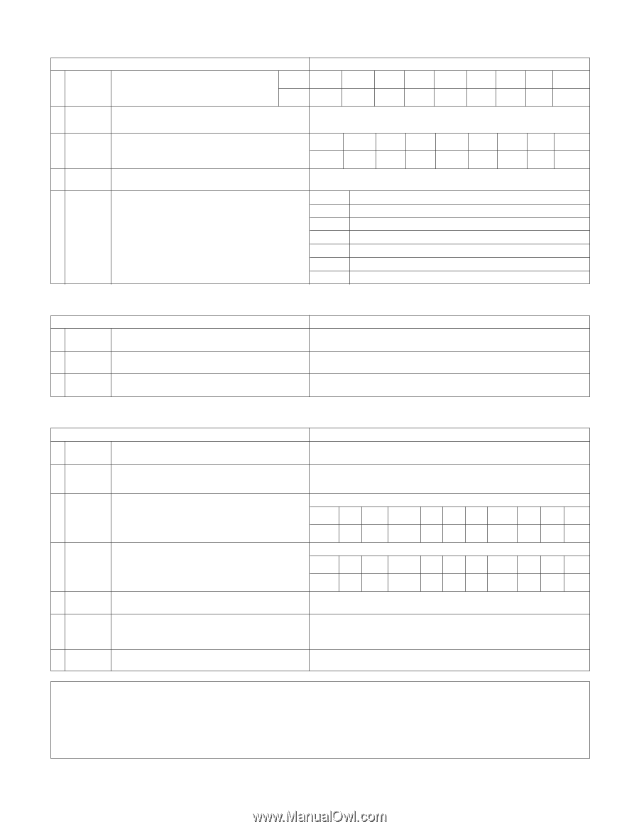
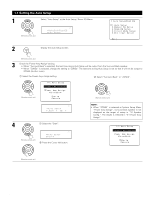
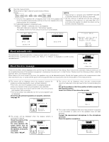
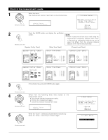
3.Input Setup 1 Digital In Assignment Ext. In 2 Subwoofer Level 3 Component In Assign Input Setup This assigns the digital input jacks for the different input sources. Input source Digital Inputs CD DVD VDP COAX1 COAX2 OPT1 Default settings TV DBS V. AUX VCR-1 VCR-2 CDR/TAPE OFF OPT2 OPT5 OPT3 OFF OPT4 Set the Ext. In Subwoofer terminal playback level. Subwoofer = +15 dB DVD VDP TV DBS VCR-1 VCR-2 V. AUX - - This assigns the color difference (component) video input jacks for the different input sources. VIDEO1 NONE VIDEO2 VIDEO3 NONE NONE NONE - - 4 Video Input Mode 5 Auto Tuner Presets Set the input signal to be output from the monitor output terminal. AUTO FM stations are received automatically and stored in the memory. A1 ~ A8 B1 ~B8 C1 ~C8 D1 ~D8 E1 ~E8 F1 ~F8 G1 ~G8 87.5/89.1/98.1/107.9/90.1/90.1/90.1/90.1 MHz 520/600/1000/1400/1500/1710 kHz/90.1/90.1 MHz 90.1 MHz 90.1 MHz 90.1 MHz 90.1 MHz 90.1 MHz 4.Advanced Playback 1 Audio Delay Advanced Playback Set the audio delay to delay time the sound and synchronize it with the picture. 2 Dolby Digital Setup Turn the audio compression on or off when down-mixing Dolby Digital signals. 3 Auto Surround Mode Set the Auto surround mode function. Default settings 0 ms OFF Auto Surround Mode = ON 5.Option Setup Option Setup Default settings 1 Power AMP Assignment Set this to switch the surround back channel's power amplifier for use for zone2. Surround Back 2 Zone2 vol. Level 3 Trigger Out1 Setup This sets the output level the zone2 output jacks. This menu is not displayed, when "ZONE2" is selected at Option Setup "Power Amp Assign". Variable ZONE=MAIN Set the Trigger Out1 output for the each input sources. PHONO CD TUNER CDR/TAPE DVD VDP TV OFF OFF OFF OFF ON ON ON 4 Trigger Out2 Setup Set the Trigger Out2 output for the each input sources. ZONE=2 PHONO CD TUNER CDR/TAPE DVD VDP TV ON ON ON ON ON ON ON DBS VCR-1 VCR-2 V. AUX ON ON ON ON DBS VCR-1 VCR-2 V. AUX ON ON ON ON 5 Muting Level This sets the amount of attenuation at audio output muting. ---dB(minimum) 6 On Screen Display 7 Setup Lock This sets whether or not to display the on-screen display that appears on the monitor screen when the controls on the remote control unit or main unit are operated. A setting to prevent flickering. Set whether or not to lock the system setup settings so that they cannot be changed. On Screen Display = ON / Mode 1 Setup Lock = OFF NOTES: • The on-screen display signals are output with priority to the S-VIDEO MONITOR OUT jack during playback of a video component. For example, if the TV monitor is connected to both the AVR-2805/985's S-Video and video monitor output jacks and signals are input to the AVR-2805/985 from a video source (VDP, etc.) connected to both the S-Video and video input jacks, the on-screen display signals are output with priority to the S-Video monitor output. If you wish to output the signals to the video monitor output jack, do not connect a cord to the S-VIDEO MONITOR OUT jack. (For details, see page 49.) • The AVR-2805/985's on-screen display function is designed for use with high resolution monitor TVs, so it may be difficult to read small characters on TVs with small screens or low resolutions. • The setup menu is not displayed when headphone are being used. 19
-
 1
1 -
2
-
3
-
4
-
5
-
6
-
7
-
8
-
9
-
10
-
11
-
12
-
13
-
 14
14 -
 15
15 -
 16
16 -
 17
17 -
 18
18 -
 19
19 -
 20
20 -
 21
21 -
 22
22 -
 23
23 -
 24
24 -
25
-
26
-
27
-
28
-
29
-
30
-
31
-
32
-
33
-
34
-
35
-
36
-
37
-
38
-
39
-
40
-
41
-
42
-
43
-
44
-
45
-
46
-
47
-
48
-
49
-
50
-
51
-
52
-
53
-
54
-
55
-
56
-
57
-
58
-
59
-
60
-
61
-
62
-
63
-
64
-
65
-
66
-
67
-
68
-
69
-
70
-
71
-
72
-
73
-
74
-
75
-
76
-
77
-
78
-
79
-
80
-
81
-
82
-
83
-
84
-
85
-
86
-
87
-
88
-
89
-
90
-
91
-
92
-
93
-
94
-
95
-
96
-
97
-
98
-
99
-
100
 |
 |