Dewalt D21002 Instruction Manual - Page 2
RÈgles De SÉcuritÉ GÉnÉrales - drill
 |
View all Dewalt D21002 manuals
Add to My Manuals
Save this manual to your list of manuals |
Page 2 highlights
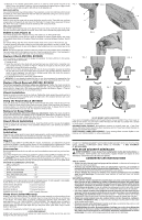
9. Because of the variable speed switch, there is no need to center punch the point to be drilled. Use a slow speed to start the hole and accelerate by squeezing the trigger harder when the hole is deep enough to drill without the bit skipping out. DRILLING IN METAL Use a cutting lubricant when drilling metals. The exceptions are cast iron and brass which should be drilled dry. The cutting lubricants that work best are sulfurized cutting oil or lard oil; bacongrease will also serve the purpose. DRILLING IN WOOD Holes in wood can be made with the same twist drills used for metal. These bits may overheat unless pulled out frequently to clear chips from the flutes. For larger holes, use power drill wood bits. Work that is apt to splinter should be backed up with a block of wood. DRILLING IN MASONRY Use carbide tipped masonry bits at low speeds. Keep even force on the drill but not so much that you crack the brittle materials. A smooth, even flow of dust indicates the proper drilling rate. Bubble Level (Figure 2) Your drill is equipped with a bubble level (C) that assists you in drilling level holes. For horizontal drilling, tilt the drill up or down as required so that the bubble floats in the center of the parallel lines drawn on the glass. When the bubble is centered between the lines, the drill is level. For vertical drilling, align the drill so that the bubble floats in the center of the bull's-eye, (D). To assure accuracy, first place a level on your work piece and position it so that it is level. Then, when the drill reads level, the two will be aligned. (Any bubble level can only indicate level to the earth's surface). NOTE: The level is filled with mineral oil that may cause minor skin irritation when contacted. If the level breaks and this fluid gets on your skin, rinse thoroughly with water. If any liquid gets in your eyes, rinse thoroughly with water and call a physician immediately. Keyless Chuck (D21008, D21009) Your tool features a keyless chuck for greater convenience. To insert a drill bit or other accessory, follow the steps listed below. 1. Unplug the drill. 2. Grasp the rear half of the chuck with one hand and use your other hand to rotate the front half counterclockwise, as shown in Figure 4. Rotate far enough so that the chuck opens sufficiently to accept the desired accessory. 3. Insert the bit or other accessory about 3/4" into the chuck and tighten securely by holding the rear half of the chuck and rotating the front portion in the clockwise direction. When the chuck is nearly tightened, you will hear a clicking sound. After 4-6 clicks, the chuck is securely tightened around the accessory. 4. To release the accessory, repeat step 2 listed above. WARNING: Do not attempt to tighten drill bits (or any other accessory) by gripping the front part of the chuck and turning the tool on. Damage to the chuck and personal injury may result. Keyless Chuck Removal (D21008, D21009) Turn off and unplug the drill before making any adjustments. Tighten the chuck around the shorter end of a hex key (not supplied) of 1/4" or greater size. Using a soft hammer or piece of wood, strike the longer end in the counterclockwise direction, as shown in Figure 4. This will loosen the chuck so that it can be unscrewed by hand. Chuck Installation Screw the chuck on by hand as far as it will go. Tighten the chuck around the shorter end of a 1/4" or larger hex key (not supplied) strike the longer end in the clockwise direction with a soft hammer, as shown in Figure 5. Using the Keyed Chuck (D21002) Open the chuck jaws by turning collar with by hand and insert the shank of the bit about 3/4" into chuck. Tighten the chuck collar by hand. Place chuck key in each of the three holes, and tighten in clockwise direction. It's important to tighten chuck with all three holes. To release the bit, turn the chuck counterclockwise in just one hole, then loosen the chuck by hand. Removal of Keyed Chuck Turn off and unplug the drill before making any adjustments. Tighten the chuck around the shorter end of a hex key (not supplied) of 1/4" or greater size. Strike the key sharply in the counterclockwise direction when viewed from the front of the tool as shown in Figure 6. This will loosen the chuck so that it can be removed by hand. Keyed Chuck Installation Screw the chuck on by hand as far as it will go. Insert the shorter end of a hex key (not supplied) of 1/4" or greater size and strike it in the clockwise direction with a soft hammer, as shown in Figure 7. MAINTENANCE Lubrication When the tool is taken apart for motor brush replacement a small amount of grease should be added (or redistributed from that remaining in housing) to the gears. The ball bearings used in this tool are lubricated during manufacture and require no lubrication. Repairs To assure product SAFETY and RELIABILITY, repairs, maintenance, and adjustment should be performed by DEWALT certified service centers or other qualified service organizations. These service organizations service DEWALT tools always using DEWALT replacement parts. Accessories Recommended accessories for use with your tool are available at extra cost from your local service center. If you need assistance in locating any accessory, please contact DEWALT Industrial Tool Co., 701 East Joppa Road, Baltimore, MD 21286 or call 1-800-4-DEWALT (1-800-433-9258). CAUTION: The use of any other accessory might be hazardous.) For safety in use, the following accessories should be used only in sizes up to the maximums shown in the table below. MAXIMUM RECOMMENDED CAPACITIES DRILL CAPACITY 3/8" R.P.M. 0-2500 BITS, METAL DRILLING 3/8" WOOD, FLAT BORING 1" BITS, MASONRY DRILLING 1/2" HOLE SAWS 1-1/8" ACCESSORY MUST BE RATED FOR USE AT SPEED EQUAL TO OR HIGHER THAN NAMEPLATE R.P.M. OF TOOL WITH WHICH IT IS BEING USED. WIRE WHEEL BRUSHES 4" Diameter Maximum WIRE CUP BRUSHES 3" Diameter Maximum BUFFING WHEELS 3" Diameter Maximum RUBBER BACKING PADS 4-5/8" Diameter Maximum Three Year Limited Warranty DEWALT will repair, without charge, any defects due to faulty materials or workmanship for three years from the date of purchase. This warranty does not cover part failure due to normal wear or tool abuse. For further detail of warranty coverage and warranty repair information, visit www.dewalt.com or call 1-800-4-DEWALT (1-800-433-9258). This warranty does not apply to accessories or damage caused where repairs have been made or attempted by others. This warranty gives you specific legal rights and you may have other rights which vary in certain states or provinces. In addition to the warranty, DEWALT tools are covered by our: 1 YEAR FREE SERVICE DEWALT will maintain the tool and replace worn parts caused by normal use, for free, any time during the first year after purchase. FIG. 1 B A FIG. 2 FIG. 3 C D FIG. 4 FIG. 5 FIG. 6 FIG. 7 90 DAY MONEY BACK GUARANTEE If you are not completely satisfied with the performance of your DEWALT Power Tool, Laser, or Nailer for any reason, you can return it within 90 days from the date of purchase with a receipt for a full refund - no questions asked. RECONDITIONED PRODUCT: Reconditioned product is covered under the 1 Year Free Service Warranty. The 90 Day Money Back Guarantee and the Three Year Limited Warranty do not apply to reconditioned product. FREE WARNING LABEL REPLACEMENT: If your warning labels become illegible or are missing, call 1-800-4-DEWALT for a free replacement. POUR TOUT RENSEIGNEMENT SUPPLÉMENTAIRE SUR CET OUTIL OU TOUT AUTRE OUTIL DEWALT, COMPOSER SANS FRAIS LE NUMÉRO : 1 800 4-DEWALT (1 800 433-9258) RÈGLES DE SÉCURITÉ GÉNÉRALES AVERTISSEMENT! Vous devez lire et comprendre toutes les instructions. Le non-respect, même partiel, des instructions ci-après entraîne un risque de choc électrique, d'incendie et/ou de blessures graves. CONSERVEZ CES INSTRUCTIONS AIRE DE TRAVAIL • Veillez à ce que l'aire de travail soit propre et bien éclairée. Le désordre et le manque de lumière favorisent les accidents. • N'utilisez pas d'outils électriques dans une atmosphère explosive, par exemple en présence de liquides, de gaz ou de poussières inflammables. Les outils électriques créent des étincelles qui pourraient enflammer les poussières ou les vapeurs. • Tenez à distance les curieux, les enfants et les visiteurs pendant que vous travaillez avec un outil électrique. Ils pourraient vous distraire et vous faire faire une fausse manoeuvre. SÉCURITÉ ÉLECTRIQUE • Les outils mis à la terre doivent être branchés dans une prise correctement installée et mise à la terre tel que l'indiquent les codes et règlements en vigueur. Ne jamais retirer la broche de mise à la terre ou modifier la prise en aucune façon. Ne pas utiliser de fiche d'adaptation. Consulter un électricien qualifié s'il y a un doute en ce qui concerne la mise à la terre de la prise. En cas de mauvais fonctionnement ou de bris des outils, la mise à la terre offre un chemin de faible résistance afin d'empêcher l'électrocution de l'utilisateur. • Les outils à double isolation sont équipés d'une fiche polarisée (une des lames est plus large que l'autre), qui ne peut se brancher que d'une seule façon dans une prise polarisée Ne modifiez pas la fiche de l'outil. La double isolation élimine le besoin d'un cordon d'alimentation à trois fils avec mise à la terre ainsi que d'une prise de courant mise à la terre. • Évitez tout contact corporel avec des surfaces mises à la terre (tuyauterie, radiateurs, cuisinières, réfrigérateurs, etc.). Le risque de choc électrique est plus grand si votre corps est en contact avec la terre. • N'exposez pas les outils électriques à la pluie ou à l'eau. La présence d'eau dans un outil électrique augmente le risque de choc électrique. • Ne maltraitez pas le cordon. Ne transportez pas l'outil par son cordon et ne débranchez pas la fiche en tirant sur le cordon. N'exposez pas le cordon à la chaleur, à des huiles, à des arêtes vives ou à des pièces en mouvement. Remplacez immédiatement un cordon endommagé. Un cordon endommagé augmente le risque de choc électrique.
-
 1
1 -
 2
2 -
 3
3 -
 4
4 -
 5
5
 |
 |
