Dewalt D28755 Instruction Manual - Page 2
Rotating the Gear Case Fig. 2, 3 - 14 concrete cut off saw
 |
View all Dewalt D28755 manuals
Add to My Manuals
Save this manual to your list of manuals |
Page 2 highlights
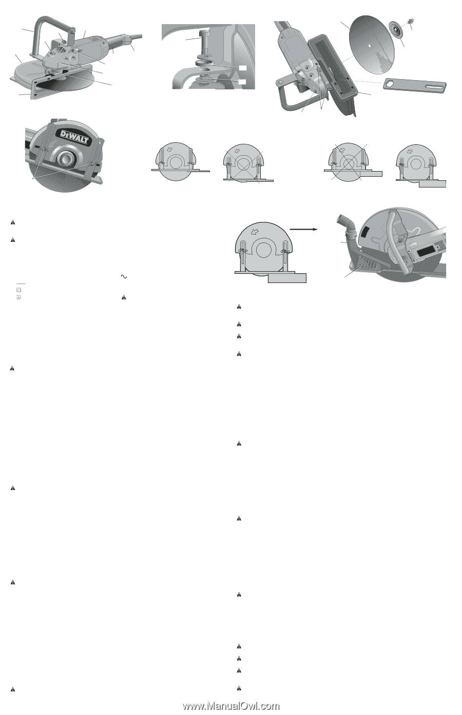
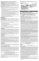
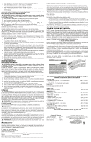
FIG. 2 F D J P E FIG. 5 FIG. 3 G J H A N K O L M FIG. 6 METALS OR THIN MATERIAL MÉTAUX OU MATÉRIAUX MINCES METALES O MATERIAL FINO FIG. 4 S Q R E P M FIG. 7 MASONRY MATERIAL PRODUIT DE MAÇONNERIE MATERIAL DE MAMPOSTERÍA C YES / OUI / SÍ • Avoid prolonged contact with dust from power sanding, sawing, grinding, drilling, and other construction activities. Wear protective clothing and wash exposed areas with soap and water. Allowing dust to get into your mouth, eyes, or lay on the skin may promote absorption of harmful chemicals. WARNING: Use of this tool can generate and/or disburse dust, which may cause serious and permanent respiratory or other injury. Always use NIOSH/OSHA approved respiratory protection appropriate for the dust exposure. Direct particles away from face and body. CAUTION: Wear appropriate personal hearing protection during use. Under some conditions and duration of use, noise from this product may contribute to hearing loss. • The label on your tool may include the following symbols. The symbols and their definitions are as follows: V volts A amperes Hz hertz W watts min minutes direct current alternating current no no load speed Class II Construction .../min revolutions per minute earthing terminal safety alert symbol SAVE THESE INSTRUCTIONS COMPONENTS Refer to Figure 1 for a complete list of components. ASSEMBLY Rotating the Gear Case (Fig. 2, 3) NOTE: This machine is assembled at the factory with the spindle on right side of the unit for right handed operation. CONVERSION FROM RIGHT-HANDED TO LEFT-HANDED CAUTION: Turn off and unplug the tool before making any adjustments or removing or installing attachments or accessories. Be sure the trigger switch is in the OFF position. 1. Place unit on a firm, flat work surface. 2. Remove bail handle (F) by removing 2 hex bolts (J), the top insulators (K) and the bottom insulators (L). 3. Remove guard by removing guard mounting nuts (M). 4. Remove the four gear case mounting screws (N). 5. Rotate gear case 180˚ without pulling gear case (O) away from the body of the tool. NOTE: If the gear case and motor housing become separated by more than 1/8", the tool must be serviced and re-assembled by a DEWALT service center. Failure to have the tool serviced may cause brush, motor and bearing failure. 6. Replace the four gear case mounting screws (N) and tighten firmly to 30 in-lb (3.4 Nm). 7. Reattach the guard so the shoe faces in the same direction as the trigger switch handle (H). Be sure the guard is on the spindle bearing hub as far as it will go and both guard tabs engage the slot in the spindle bearing hub. Tighten guard mounting nuts (M) securely to 50 in-lb (5.7 Nm). 8. Replace the bail handle with the bottom insulators (L), top insulators (K) and the two hex bolts (J) then tighten securely to 75 in-lb (8.5 Nm). Refer to Figure 2 for orientation of the bail handle. WARNING: Plastic insulators must be assembled to hex bolts and bracket as shown in Figure 3. Failure to do so may result in electric shock injury. OPERATION Motor Be sure your power supply agrees with the nameplate marking. Voltage decrease of more than 10% will cause loss of power and overheating. All DEWALT tools are factory tested; if this tool does not operate, check the power supply. Spindle Lock Button (Fig. 4) The spindle lock button (P) is used to lock the spindle when changing accessories. To engage the spindle lock button, disconnect the tool from the power supply and be sure switch is in OFF position. Depress the spindle lock button and turn the wheel and spindle until the lock button engages the spindle. Use supplied wrench to unscrew the spindle bolt (Q) and remove or mount accessories. Spindle threads are right hand. Installing Abrasive Wheels (Fig. 4, 5) CAUTION: Turn off and unplug the tool before making any adjustments or removing or installing attachments or accessories. Be sure the trigger switch is in the OFF position. 1. Lay unit on a firm surface with bottom of shoe (E) facing up. 2. Loosen depth adjustment wing nuts (C), move shoe to allow easiest access to spindle nut, then tighten wing nuts to hold shoe in place. 3. Using supplied wrench, remove spindle bolt (Q), outer clamp washer (R) and used wheel (S) if one is installed. Hold spindle from turning with spindle lock button. Spindle threads are right hand. 4. Slip wheel (S) through bottom of shoe and slip wheel over spindle. Be sure wheel goes over 1" pilot diameter. Slip on outer clamp washer (R). Be sure outer clamp washer (R) engages flats on spindle. Thread bolt (Q) into spindle. 5. Engage spindle lock button and tighten spindle bolt (Q) with wrench. Do not over tighten spindle bolt. 6. Turn wheel by hand to ensure it is properly centered. The wheel should not hit the shoe or guard. 7. Be sure to readjust shoe for proper depth of cut. Firmly tighten the depth adjustment wing nuts (C). CAUTION: Only use 14" Type 1 wheels with 1" arbor hole with this tool. Never force a wheel onto the machine or alter the size of the arbor hole. NO / NON / NO FIG. 8 NO / NON / NO FIG. 9 DIRECTION OF CUT SENS DE COUPE DIRECCIÓN U DE CORTE YES / OUI / SÍ T Depth of Cut (Fig. 6, 7) WARNING: Edge cutting can be performed only with wheels that are designed and specified for this purpose. Protect yourself during edge cutting by directing the open side of the guard toward a surface. WARNING: Wheels used for cutting may break or kick back if they bend or twist while the tool is being used to do cut-off work. WARNING: Do not use edge cutting wheels for surface grinding applications because these wheels are not designed for side pressures encountered with surface grinding. Wheel breakage and injury may result. CAUTION: Turn off and unplug the tool before making any adjustments or removing or installing attachments or accessories. Be sure the trigger switch is in the OFF position. The depth of cut can be adjusted by loosening the two depth adjustment wing nuts (C) on the outside of the guard to change the position of the shoe. Using the slot in the wrench (provided) securely tighten the wing nuts. TO CUT METALS AND THIN MATERIALS When cutting metals and other thin materials, adjust shoe for maximum depth of cut as shown in Figure 6. TO CUT STONE OR MASONRY MATERIALS Set the wheel exposure to about 1/2" (13mm) beyond the shoe. For many applications, the material will readily break along the 1/2" (13mm) deep scored line. If a deeper cut is needed, increase the depth of cut in approximately 1/2" (13mm) increments between cuts (Fig. 7). To Operate (Fig. 2, 8) CAUTION: Before attempting to start, grasp tool firmly with both hands before lifting. 1. Grasp trigger switch handle (H) and bail handle (F) firmly. 2. Line up wheel with material to be cut. Be sure nothing is near or in line with the wheel. 3. Depress trigger lock-off button (I) and subsequently depress and hold trigger switch (A) then slowly feed wheel into work with firm pressure. Keep the shoe (E) firmly and squarely against the work. Do not force the tool. For maximum efficiency and wheel life, keep the wheel speed high. 4. Always cut in the direction of wheel rotation (Fig. 8). If cutting in the opposite direction of wheel rotation, the tool may climb out of cut and may be difficult to control. 5. To stop tool, release trigger switch (A). Maintain control of tool until blade comes to a complete stop. Applications WARNING: NEVER cut magnesium with this tool. Magnesium particles may ignite causing personal injury. • 1/8" (3mm) maximum gauge sheet metal • Concrete, cinder blocks and bricks • Reinforcing rod; generally under 3/4" (19mm) diameter • 1/8" (3mm) diameter concrete wire mesh • Corrugated floor and ceiling form (concrete forms) • Electrical conduit 1/8" (3mm) wall thickness • 1/8" (3mm) maximum thick structural forms such as channel, angles, plate, etc. NOTE: The cutting of materials heavier than those listed above are not recommended due to the possibility of electrical overloading. TO ADJUST ANGLE OF GUARD CAUTION: Turn off and unplug the tool before making any adjustments or removing or installing attachments or accessories. Be sure the trigger switch is in the OFF position. 1. Loosen the guard mounting nuts (M), shown in Figure 2. 2. Grasp the guard firmly and rotate to desired angle. 3. Tighten clamp nuts to lock guard in position. Installing Dust Duct Attachment (Fig. 9) NOTE: The dust duct attachment is not included with all models. WARNING: Never use dust duct attachment when cutting metal or material that creates sparks while cutting. WARNING: Open view port (T) will allow some debris to pass out of cutting area. Always wear eye protection when using this tool. WARNING: Static electricity can be created when using the dust duct. Use of vacuum increases the potential for static charge build-up. To minimize static charge use only antistatic, static dissipative or separately grounded vacuum hose. CAUTION: Turn off and unplug the tool before installing or removing the dust duct attachment. Be sure the trigger is in the OFF position.
-
 1
1 -
 2
2 -
 3
3 -
 4
4 -
 5
5 -
 6
6 -
 7
7
 |
 |