Dewalt DWD525K Instruction Manual - Page 2
Depth Rod, MAINTENANCE, Cleaning, Lubrication, Accessories, Three Year Limited Warranty - drill
 |
View all Dewalt DWD525K manuals
Add to My Manuals
Save this manual to your list of manuals |
Page 2 highlights
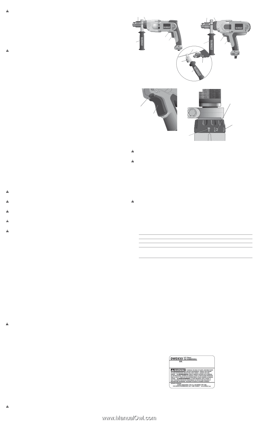
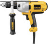
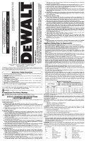
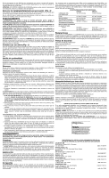
COMPONENTS (FIG. 1) WARNING: Never modify the power tool or any part of it. Damage or personal injury could result. A. Trigger switch D. Speed/Mode selector collar B. Reversing lever E. Side handle C. Chuck INTENDED USE These heavy-duty hammerdrills are designed for professional drilling and hammerdrilling. DO NOT use under humid conditions or in presence of flammable liquids or gases. These heavy-duty hammerdrills are professional power tools. DO NOT let children come into contact with the tool. Supervision is required when inexperienced operators use this tool. Side Handle (Fig. 1) WARNING: To reduce the risk of personal injury, ALWAYS operate the tool with the side handle properly installed. Failure to do so may result in the side handle slipping during tool operation and subsequent loss of control. Hold tool with both hands to maximize control. A side handle (E) is supplied with this hammerdrill. It clamps to the front of the gear case as shown in Figure 1 and can be rotated 360˚ for right- or left- hand use. After the side handle is rotated into position, it should be pushed rearward until the slots (F) on the lip of the side handle are aligned and fully engaged with the projecting tabs (G) on the underside of the gear case. The side handle is then securely clamped by turning clockwise until tight. Trigger Switch (Fig. 2) To start hammerdrill, depress the trigger switch (A). To stop hammerdrill, release the trigger switch. VARIABLE SPEED TRIGGER SWITCH (FIG. 2) The variable speed trigger switch (A) permits speed control. The farther the trigger switch is depressed, the higher the speed of the hammerdrill. NOTE: Use lower speeds for starting holes, drilling in plastics or ceramics or driving screws. REVERSING LEVER (FIG. 2) The reversing lever (B), located above the trigger switch, changes the direction of rotation of the hammerdrill and is used when backing out screws and jammed drill bits. To operate the tool in reverse, release the trigger switch and push the lever to the left (when viewed from the chuck end). To operate the drill in forward, release the trigger switch and push the lever to the right (when viewed from the chuck end). Return the reversing lever to the forward position after all operations in reverse are completed. High/Low Speed Operation (Fig. 1, 3) The two speed gear drive in the dual range hammerdrill permits effective operation over an extended range of applications with greater selection of accessories. For LOW SPEED operation, turn the collar (D) to the drill bit symbol for drilling position 1. For HIGH SPEED operation, turn the collar (D) to the drill bit symbol for drilling position 2. The gear train has been designed for shifting only when the unit is off. It may be necessary however, to rotate the chuck slightly by hand to align the gears while turning the collar. CAUTION: DO NOT ATTEMPT TO CHANGE SPEEDS by turning the collar when the tool is running. Doing so will damage the gear train. Hammer/Drill Selector (Fig. 3) To switch the tool from the drilling mode to the hammering mode (or vice-versa) rotate the collar (D) to the applicable symbol as shown in Figure 3. Turn the collar (D) to the drill bit symbol for drilling or to the hammer symbol for hammerdrilling, as shown in the figure. OPERATION WARNING: To reduce the risk of serious personal injury, turn tool off and disconnect tool from power source before making any adjustments or removing/installing attachments or accessories. WARNING: To reduce the risk of personal injury, ALWAYS ensure workpiece is anchored or clamped firmly. If drilling thin material, use a wood "back-up" block to prevent damage to the material. WARNING: To reduce the risk of personal injury, ALWAYS operate the tool with the side handle properly installed. Failure to do so may result in the side handle slipping during tool operation and subsequent loss of control. Hold tool with both hands to maximize control. WARNING: Do not attempt to tighten or loosen drill bits (or any other accessory) by gripping the front part of the chuck and turning the tool on. Damage to the chuck and personal injury may occur. WARNING: Burn Hazard. ALWAYS wear gloves when changing bits. Accessible metal parts on the tool and bits may get extremely hot during operation. Small bits of broken material may damage bare hands. Keyed Chucks (Fig. 1) Open chuck jaws by turning collar with fingers and insert shank of bit about 3/4" (19 mm) into chuck (C). Tighten chuck collar by hand. Place chuck key in each of the three holes, and tighten in clockwise direction. It's important to tighten chuck with all three holes to prevent slippage. To release bit, turn chuck key counterclockwise in just one hole, then loosen the chuck by hand. Any authorized DEWALT service center can install a keyless chuck in place of a keyed chuck. Depth Rod To adjust the depth rod (H), loosen the handle (E) and move rod so that the distance between the end of the rod and the end of the bit equals the desired drilling depth. When drilling with depth rod, stop when end of rod reaches surface of material. Drilling Turn the collar to the drill bit symbol for drilling or to the hammer symbol for hammerdrilling. Install and tighten the desired drill bit in the chuck. DRILLING OPERATION Select the desired speed/torque range using the speed selector collar to match the speed and torque to the planned operation. 1. For WOOD, use twist bits, spade bits, power auger bits or hole saws. For METAL, use highspeed steel twist drill bits or hole saws. Use a cutting lubricant when drilling metals. The exceptions are cast iron and brass which should be drilled dry. For MASONRY, use carbidetipped bits or masonry bits. A smooth, even flow of dust indicates the proper drilling rate. 2. Always apply pressure in a straight line with the bit. Use enough pressure to keep the drill bit biting, but do not push hard enough to stall the motor or deflect the bit. 3. Hold tool firmly with both hands to control the twisting action of the drill. WARNING: Drill may stall if overloaded causing a sudden twist. Always expect the stall. Grip the drill firmly with both hands to control the twisting action and avoid injury. 4. IF DRILL STALLS, it is usually because it is being overloaded. RELEASE TRIGGER IMMEDIATELY, remove drill bit from work, and determine cause of stalling. DO NOT CLICK TRIGGER OFF AND ON IN AN ATTEMPT TO START A STALLED DRILL - THIS CAN DAMAGE THE DRILL. 5. To minimize stalling or breaking through the material, reduce pressure on drill and ease the bit through the last fractional part of the hole. 6. Keep the motor running when pulling the bit back out of a drilled hole. This will help prevent jamming. 7. With variable speed drills there is no need to center punch the point to be drilled. Use a slow speed to start the hole and accelerate by squeezing the trigger harder when the hole is deep enough to drill without the bit skipping out. HAMMERDRILL OPERATION 1. When drilling, use just enough force on the hammer to keep it from bouncing excessively or "rising" off the bit. Too much force will cause slower drilling speeds, overheating, and a lower drilling rate. 2. Drill straight, keeping the bit at a right angle to the work. Do not exert side pressure on the bit when drilling as this will cause clogging of the bit flutes and a slower drilling speed. 3. When drilling deep holes, if the hammer speed starts to drop off, pull the bit partially out of the hole with the tool still running to help clear debris from the hole. 4. For masonry, use carbide-tipped bits or masonry bits. A smooth even flow of dust indicates the proper drilling rate. MAINTENANCE WARNING: To reduce the risk of serious personal injury, turn tool off and disconnect tool from power source before making any adjustments or removing/installing attachments or accessories. FIG. 1 CD DWD520 DWD525 CD B E A B E A H F G E FIG. 2 FIG. 3 B shown in forward position illustré en position avant mostrada en posición adelantada A HAMMER SETTING RÉGLAGE MARTELAGE AJUSTE DEL MARTILLO HIGH SPEED DRILL SETTING RÉGLAGE PERÇAGE HAUTE VITESSE AJUSTE DE BROCA PARA ALTA VELOCIDAD LOW SPEED DRILL SETTING RÉGLAGE PERÇAGE VITESSE RÉDUITE AJUSTE DE BROCA PARA BAJA VELOCIDAD Cleaning WARNING: Blow dirt and dust out of all air vents with dry air at least once a week. Wear proper ANSI Z87.1 (CAN/CSA Z94.3) eye protection and proper NIOSH/OSHA/MSHA respiratory protection when performing this. WARNING: Never use solvents or other harsh chemicals for cleaning the non-metallic parts of the tool. These chemicals may weaken the plastic materials used in these parts. Use a cloth dampened only with water and mild soap. Never let any liquid get inside the tool; never immerse any part of the tool into a liquid. Lubrication Your tool was properly lubricated before leaving the factory. In from two to six months, depending upon use, take or send your tool to an authorized service center for a complete cleaning, inspection and lubrication. Tools used constantly on production jobs will need relubrication more often. Also, tools "out of service" for long periods should be relubricated before being put back to work. Accessories WARNING: Since accessories, other than those offered by DEWALT, have not been tested with this product, use of such accessories with this tool could be hazardous. To reduce the risk of injury, only DEWALT, recommended accessories should be used with this product. Recommended accessories for use with your tool are available at extra cost from your local dealer or authorized service center. If you need assistance in locating any accessory, please contact DEWALT Industrial Tool Co., 701 East Joppa Road, Baltimore, MD 21286, call 1-800-4-DEWALT (1-800-433-9258) or visit our website www.dewalt.com. MAXIMUM RECOMMENDED CAPACITIES DWD520 DWD525 CHUCK CAPACITY 1/2" (13 mm) 1/2" (13 mm) R.P.M. 0-1200 / 0-3500 0-1200 / 0-3500 BITS, METAL DRILLING 1/2" (13 mm) low speed 1/2" (13 mm) low speed WOOD, FLAT BORING 1-1/2" (40 mm) 1-1/2" (40 mm) BITS, MASONRY DRILLING optimum maximum 3/16"-3/8" (5-10 mm) 3/4" (20 mm) 3/16"-7/16" (10- 11 mm) 3/4" (20 mm) Repairs To assure product SAFETY and RELIABILITY, repairs, maintenance and adjustments (including brush inspection and replacement) should be performed by a DEWALT factory service center, a DEWALT authorized service center or other qualified service personnel. Always use identical replacement parts. Three Year Limited Warranty DEWALT will repair, without charge, any defects due to faulty materials or workmanship for three years from the date of purchase. This warranty does not cover part failure due to normal wear or tool abuse. For further detail of warranty coverage and warranty repair information, visit www.dewalt.com or call 1-800-4-DEWALT (1-800-433-9258). This warranty does not apply to accessories or damage caused where repairs have been made or attempted by others. This warranty gives you specific legal rights and you may have other rights which vary in certain states or provinces. In addition to the warranty, DEWALT tools are covered by our: 1 YEAR FREE SERVICE DEWALT will maintain the tool and replace worn parts caused by normal use, for free, any time during the first year after purchase. 90 DAY MONEY BACK GUARANTEE If you are not completely satisfied with the performance of your DEWALT Power Tool, Laser, or Nailer for any reason, you can return it within 90 days from the date of purchase with a receipt for a full refund - no questions asked. LATIN AMERICA: This warranty does not apply to products sold in Latin America. For products sold in Latin America, see country specific warranty information contained either in the packaging, call the local company or see website for warranty information. FREE WARNING LABEL REPLACEMENT: If your warning labels become illegible or are missing, call 1-800-4-DEWALT for a free replacement.
-
 1
1 -
 2
2 -
 3
3 -
 4
4 -
 5
5 -
 6
6 -
 7
7
 |
 |