Dewalt DWE4011 Instruction Manual - Page 13
OPERATION, Guards and Flanges, Switches - one touch guard be removed
 |
View all Dewalt DWE4011 manuals
Add to My Manuals
Save this manual to your list of manuals |
Page 13 highlights
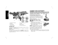
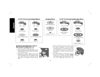
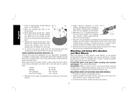
English guard collar. This insures that the guard is secure. The guard can be repositioned the opposite direction by depressing the guard release lever. 6. To remove the guard, follow steps 1-3 of these instructions in reverse. NOTE: Edge grinding and cutting can be performed with Type 27 wheels designed and specified for this purpose; 1/4" (6.35 mm) thick wheels are designed for surface grinding while 1/8" (3.17 mm) wheels are designed for edge grinding. Cutting can also be performed by using a Type 1 wheel and a Type 1 guard. OPERATION WARNING: To reduce the risk of injury, turn unit off and disconnect it from power source before installing and removing accessories, before adjusting or when making repairs. An accidental start-up can cause injury. Guards and Flanges It is important to choose the correct guards and flanges to use with the grinder accessories. See page 9-10 and this page for the correct accessories. NOTE: Edge grinding and cutting can be performed with Type 27 wheels designed and specified for this purpose. WARNING: Accessories must be rated for at least the speed recommended on the tool warning label. Wheels and other accessories running over rated accessory speed may burst and cause injury. Every unthreaded accessory must have a 7/8" arbor hole. If it does not, it may have been designed for a circular saw and should not be used. Use only the accessories shown on pages 9-10. Accessory ratings must be above listed minimum wheel speed as shown on tool nameplate. Switches CAUTION: Hold the side handle and body of the tool firmly to maintain control of the tool at start up and during use and until the wheel or accessory stops rotating. Make sure the wheel has come to a complete stop before laying the tool down. NOTE: To reduce unexpected tool movement, do not switch the tool on or off while under load conditions. Allow the grinder to run up to full speed before touching the work surface. Lift the tool from the surface before turning the tool off. Allow the tool to stop rotating before putting it down. SLIDER SWITCH (FIG. 6) FIG. 6 WARNING: Before connecting the tool to a power supply, be sure the slider switch is in the off position by pressing the rear part of the switch and releasing. Ensure the slider switch is in H the off position as described above after any interruption in power supply to the tool, such as the activation of a ground fault interrupter, throwing of a circuit breaker, accidental unplugging, or power failure. If the slider switch is locked on when the power is connected, the tool will start unexpectedly. To start the tool, slide the ON/OFF slider switch (H) toward the front of the tool. To stop the tool, release the ON/OFF slider switch. For continuous operation, slide the switch toward the front of the tool and press the forward part of the switch inward. To stop the tool while operating in continuous mode, press the rear part of the slider switch and release. 11
-
 1
1 -
2
-
3
-
4
-
5
-
6
-
7
-
 8
8 -
 9
9 -
 10
10 -
 11
11 -
 12
12 -
 13
13 -
 14
14 -
 15
15 -
 16
16 -
 17
17 -
 18
18 -
19
-
20
-
21
-
22
-
23
-
24
-
25
-
26
-
27
-
28
-
29
-
30
-
31
-
32
-
33
-
34
-
35
-
36
-
37
-
38
-
39
-
40
-
41
-
42
-
43
-
44
-
45
-
46
-
47
-
48
-
49
-
50
-
51
-
52
-
53
-
54
-
55
-
56
-
57
-
58
-
59
-
60
-
61
-
62
-
63
 |
 |
