EVGA 112-CK-NF70-TR User Guide - Page 8
wer Con, nnection - cpu support
 |
UPC - 843368007744
View all EVGA 112-CK-NF70-TR manuals
Add to My Manuals
Save this manual to your list of manuals |
Page 8 highlights
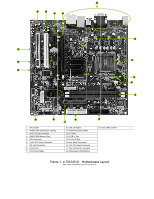
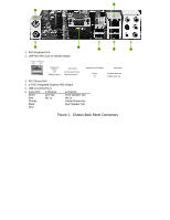
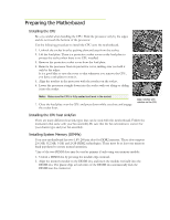
Power Connections This motherboard requires an ATX power supply. Make sure your power supply can provide enough wattage to power all the components you will be installing. 24-pin ATX Power (PWR1) PWR1 is the main power supply connector located along the edge of the board next to the DIMM slots. Make sure that the power supply cable and pins are properly aligned with the connector on the motherboard. Firmly plug the power supply cable into the connector and make sure it is secure. PWR1 connector Plug power cable from system power supply to PWR1 8-pin ATX 12V Power (PWR2) PWR2, the 4-Pin ATX 12V power connection, is used to provide power to the CPU. Align the pins to the connector and press firmly until seated. The connection is notched and will only fit in one way. FDD Connector The motherboard supports a standard 360K, 720K, 1.2M, 1.44m, and a 2.88M floppy disk drive (FDD). Connecting IDE Hard Disk Drives The IDE connector supports Ultra ATA 133/100/66 IDE hard disk drives. Connect the cable end with a single connector to the motherboard. If you install two hard disk drives, you must configure the second drive as a slave device by setting its jumper accordingly. Refer to the hard disk documentation for the jumper settings.
-
 1
1 -
2
-
 3
3 -
 4
4 -
 5
5 -
 6
6 -
 7
7 -
 8
8 -
 9
9 -
 10
10 -
 11
11
 |
 |
