EVGA 112-CK-NF70-TR User Guide - Page 9
onnecting S, onnecting I, Front Pan, B Headers, Serial ATA C, nternal Hea, nel Header, Cables, aders
 |
UPC - 843368007744
View all EVGA 112-CK-NF70-TR manuals
Add to My Manuals
Save this manual to your list of manuals |
Page 9 highlights
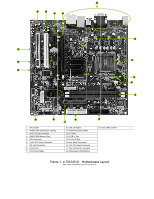
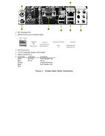
Connecting Serial ATA Cables The Serial ATA II connector is used to connect the Serial ATA II device to the motherboard. These connectors support the thin Serial ATA II cables for primary storage devices. The current Serial ATA II interface allows up to 300MB/s data transfer rate. There are four serial ATA connectors on the motherboard. These connectors support RAID 0, RAID 1. Connecting Internal Headers Please refer to #9 of in the table of Figure 1. e-7010/610i Motherboard Layout for the location of the Front Panel Headers. Front Panel Header The front panel header on this motherboard is one connector used to connect the following four cables: ‰ PWRLED Attach the front panel power LED cable to the PWR LED connector. The Power LED indicates the system's status. ‰ PWRSW Attach the power button cable from the case to these two pins. Pressing the powerbutton on the front panel turns the system on off rather than using the power supply button. ‰ HD_LED Attach the hard disk drive indicator LED cable to these two pins. The HDD indicator LED indicates the activity status of the hard disks. ‰ RESET Attach the Reset switch cable from the front panel of the case to these two pins. The system restarts when the RESET switch is pressed. Note: Some chassis do not have all four cables. Be sure to match the name on the connectors to the corresponding pins. USB Headers The motherboard contains 10-pin internal USB header connector(s). These can be used for a front panel USB connection or USB bracket.
-
 1
1 -
2
-
3
-
 4
4 -
 5
5 -
 6
6 -
 7
7 -
 8
8 -
 9
9 -
 10
10 -
 11
11
 |
 |
