Edimax ES-3308P Quick Install Guide - Page 5
Connecting to network devices, Connecting the power
 |
View all Edimax ES-3308P manuals
Add to My Manuals
Save this manual to your list of manuals |
Page 5 highlights
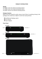
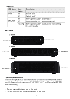
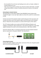
- Do not position the unit near any heating source such as a heater, radiator or in direct exposure to sun. - Take care to ensure the unit does not come into contact with water. Consider using a dehumidifier to reduce humidity and prevent moisture entering the unit. Connecting to network devices The RJ-45 ports on the switch support Auto-MDI/MDI-X which allows both straight-through or cross-over type cables to connect this switch to a workstation or hub. Connect one end of the network cable to the RJ-45 port on the rear panel, and connect the other end of the network cable to the RJ-45 port on the network device. Follow the same procedure to connect all RJ-45 ports of the switch. The UTP network cables must comply with EIA/TIA 568 specifications and Category 5 standard for data transmission. The maximum length for a UTP cable segment between the switch and connected devices is 100 meters (300ft). Once the network cable is connected to both ends and the attached network device is powered on, the green LNK/ACT LED should be lit. Connecting the power Connect the power adapter to the power connector of the unit; the green power LED on the front panel should be lit. ES-3305P/ES-3308P 5 ES-3316P
-
 1
1 -
 2
2 -
 3
3 -
 4
4 -
 5
5 -
 6
6 -
 7
7 -
 8
8
 |
 |
