Electrolux E30EW75GSS Installation Instructions
Electrolux E30EW75GSS - 30" Single Electric Wall Oven Manual
 |
UPC - 057112096308
View all Electrolux E30EW75GSS manuals
Add to My Manuals
Save this manual to your list of manuals |
Electrolux E30EW75GSS manual content summary:
- Electrolux E30EW75GSS | Installation Instructions - Page 1
For combination of this Built-in Oven with Warm & Serve Drawer see cutout dimensions specified in the Warm & Serve Drawer Installation Instructions. Figure 1 (Double Wall Oven see page 2) PRODUCT DIMENSIONS MODEL A B C (Rear wrapper) D 30" (76.2 cm) Wall Oven 30 (76.2) 29¼ (74.2) 28¼ (71 - Electrolux E30EW75GSS | Installation Instructions - Page 2
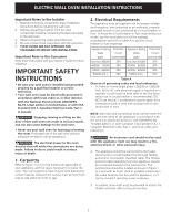
ELECTRIC WALL OVEN INSTALLATION INSTRUCTIONS Do not remove spacers on the side walls and/or on the back of the built-in oven. These spacers center the oven in the space provided. The oven must be centered to prevent excess heat buildup that may result in heat damage or fire. NOTE: 1. Base must be - Electrolux E30EW75GSS | Installation Instructions - Page 3
Important Note to the Consumer Keep these instructions with your Owner's Guide for future reference. IMPORTANT SAFETY INSTRUCTIONS • Be sure your wall oven is installed and grounded properly by a qualified installer or service technician. • Your wall oven must be electrically grounded in accordance - Electrolux E30EW75GSS | Installation Instructions - Page 4
WALL OVEN INSTALLATION INSTRUCTIONS oven control at power on. Model and Serial Number Location The serial plate is located inside the oven on the side trim. When ordering parts for or making inquires about your oven Use only connectors designed for joining copper to aluminum, and follow the - Electrolux E30EW75GSS | Installation Instructions - Page 5
ELECTRIC WALL OVEN INSTALLATION INSTRUCTIONS the bare copper ground wire to the grounded lead in the service panel. DO NOT ground to a gas supply pipe. DO NOT the bottom of the door up and toward you to disengage the hinge supports. Keep pulling the bottom of the door toward you while rotating the - Electrolux E30EW75GSS | Installation Instructions - Page 6
Weight Hazard • Use 2 or more people to move and install wall oven. • Failure to follow this instructions can result in injury or damage to the unit. The wall oven can tip when the door is opened. The mounting brackets supplied with the wall oven must be attached to the cabinet and the appliance to - Electrolux E30EW75GSS | Installation Instructions - Page 7
be capable of supporting 200 pounds (90 kg). Cut an opening in wood base to route armored cable to junction box. 4 1/2" (11.5 cm) Max.* * If no cooktop is installed directly over the oven unit, 5" (12.7 cm) maximum is allowed above the floor. 30" (76.2 cm) Wall Oven CUTOUT DIMENSIONS F. WIDTH - Electrolux E30EW75GSS | Installation Instructions - Page 8
ELECTRIC WALL OVEN INSTALLATION INSTRUCTIONS 18"(45.7 cm) Max. Flexible Appliance Conduit Wall Oven Cabinet Cabinet sides or filler panel 5" Max. 6 1/2" Min. (12.7 cm) (16.5 cm) Flare Union Flare Union 120V/60Hz Grounded Outlet Pressure Regulator Manual Shutoff Valve 4"(10 cm) Right Side of - Electrolux E30EW75GSS | Installation Instructions - Page 9
ELECTRIC WALL OVEN INSTALLATION INSTRUCTIONS 7. Checking Operation Your model is equipped with an Electronic Oven Control. Each of the functions has been factory checked before shipping. However, it is suggested that you verify the operation of the electronic oven controls once more. Refer to the - Electrolux E30EW75GSS | Installation Instructions - Page 10
la figura 1. Posiblemente encontrará que algún trabajo de carpintería será necesario. No quite los separadores de los muros laterales o/y de la parte posterior del horno empotrado. Estos espaciadores centran el horno en el espacio provisto. El horno debe estar centrado para prevenir una concentraci - Electrolux E30EW75GSS | Installation Instructions - Page 11
INSTRUCCIONES DE INSTALACIÓN PARA EL HORNO ELECTRICO DE PARED No quite los separadores de los muros laterales o/y de la parte posterior del horno empotrado. Estos espaciadores centran el horno en el espacio provisto. El horno debe estar centrado para prevenir una concentración excesiva de calor - Electrolux E30EW75GSS | Installation Instructions - Page 12
el instalador 1. Lea todas las instrucciones contenidas en este manual antes de instalar el horno. 2. Saque todo el material ltima edición en los Estados Unidos, o el Código Eléctrico Canadiense CSA Standard C22.1, Part 1, en Canadá. Pisar, apoyarse, o sentarse sobre la puerta de este horno de pared - Electrolux E30EW75GSS | Installation Instructions - Page 13
con el Código Eléctrico Nacional ANSI/ NFPA No. 70-última edición en los Estados Unidos, o el Código Eléctrico Canadiense CSA Standard C22.1, Part 1, en Canadá. En este electrodomestico se necesita un cable de toma a tierra. Este electrodoméstico viene equipado con un cable de conexión de cobre. Si - Electrolux E30EW75GSS | Installation Instructions - Page 14
vez de solamente el calibre del alambre. Apertura de bisagra puerta desemsamblada de la estufa. 5. Remueva el ajuste inferior. Remueva el ajuste inferior de la parte superior de la unidad. El ajuste debera ser instalado después. 14 - Electrolux E30EW75GSS | Installation Instructions - Page 15
graves. Instrucciones de instalación de los soportes de montaje 1. Encuentre los dos tornillos de montaje incluidos con el paquete de información. 2. Instale la abrazadera de montaje como en la figura 8. Nota: Para prevenir cualquier tipo de daño al cabinete es recomendable perforar agujeros conn - Electrolux E30EW75GSS | Installation Instructions - Page 16
de empalme para hornos de pared G H F Corte una abertura en el fondo del contrachapado, para poder encaminar el cable a la caja de empalme. Instale contrachapado de 3/4" (1.9 cm) sobre dos correderas, nivelado con la parrilla inferior. La base debe poder sostener 200 libras (90 kg). 4 1/2" (11 - Electrolux E30EW75GSS | Installation Instructions - Page 17
Gabinete del horno de pared Regulador de presión Válvula de cierre manual 4"(10 cm) Lado derecho del gabinete (para tener acceso a la válvula de cierre manual) ESCTUoFoAktDoEp GAS VhiostranodWSediadelalelpdOaovrivdeeeedwnl VisFtaroannttevriieowr Figura 13 - INSTALACION TÍPICA PARA UNA ESTUFA - Electrolux E30EW75GSS | Installation Instructions - Page 18
controles para ver el funcionamiento del horno. 1. Extraer todos los elementos de la parte interior del horno. 2. Encender el horno (Consular la Guía de Uso y al servicio Lea la sección Lista de Control de Averías en su Manual del Usuario. Esto le podrá ahorrar tiempo y gastos. Esta lista incluye - Electrolux E30EW75GSS | Installation Instructions - Page 19
pouvant causer un feu ou des dommages. NOTE: 1. La base doit pouvoir supporter 200 lbs (90.7 kg). 2. Assurez-vous que le fond du cabinet es dans les instructions d'installation du tiroir réchaud. La distance minimale requise est 41/2" (11.4 cm). Figure 1 (Pour connaître les dimensions d'un four - Electrolux E30EW75GSS | Installation Instructions - Page 20
INSTRUCTIONS D'INSTALLATION pouvant causer un feu ou des dommages. NOTE: 1. La base doit pouvoir supporter 400 lbs (181.4 kg). 2. Assurez-vous que le fond du cabinet (130.2 cm) H Entretoise NOTE: La dimension G est critique pour une bonne installation du four. Si la moulure inférieure (ventilation - Electrolux E30EW75GSS | Installation Instructions - Page 21
Consommateur Conservez ces instructions avec votre Manuel d'utilisation et d'entretien pour références futures. DIRECTIVES IMPORTANTES DE SÉCURITÉ • Assurez-vous que votre four encastré est installé et mis à la terre conformément par un installateur ou un technicien de service qualifié. • Votre four - Electrolux E30EW75GSS | Installation Instructions - Page 22
INSTRUCTIONS D'INSTALLATION POUR FOUR ENCASTRÉ ÉLECTRIQUE Par temps froid, pour protéger la Le consommateur est responsable et doit communiquer avec un installateur qualifié pour s'assurer que l'installation électrique est adéquate et conforme avec le National Electrical Code ANSI/NFPA No. 70 - Electrolux E30EW75GSS | Installation Instructions - Page 23
sa manipulation et son installation. IMPORTANT Ne soulevez pas la porte du four par la poignée. Suivre les instructions suivantes pour enlever porte, soulevez légèrement la porte et tirez-la vers vous pour dégager les supports de charnières. Continuez à tirer la porte vers vous en faisant pivoter le - Electrolux E30EW75GSS | Installation Instructions - Page 24
est ouverte. Il faut donc le fixer à l'armoire à l'aide des supports de fixation fournis afin de prévenir le basculement du four et des blessures corporelles. Instructions d'installation des supports de fixation 1. Récupérez les 2 supports et les vis de fixation compris dans l'emballage contenant la - Electrolux E30EW75GSS | Installation Instructions - Page 25
base doit pouvoir supporter 200 lbs (90 kg). 4½" (11.5 cm) Max. DIMENSIONS DE L'OUVERTURE F. LARGEUR G. PROFONDEUR H. HAUTEUR 30" (76.2 cm) 28 1/2" (72.4 cm) Min. Wall Oven 29" (73.7 cm) Max. 24" (61 cm) Min. 28 ¼" (71.8 cm) Min. 28 7/8" (73.3 cm) Max. Figure 12 - INSTALLATION TYPIQUE D'UN - Electrolux E30EW75GSS | Installation Instructions - Page 26
INSTRUCTIONS D'INSTALLATION POUR FOUR ENCASTRÉ ÉLECTRIQUE 18"(45.7 cm) Max. TABLE DE CUISSON À GAZ 5" Max. 6 1/2" Min. (12.7 Raccord cm) (16.5 cm) évasé Conduit à gaz flexible Raccord évasé Prise 120V/60Hz mise à la terre Armoire où le four est installé Côtés de l'armoire ou panneau de - Electrolux E30EW75GSS | Installation Instructions - Page 27
INSTRUCTIONS D'INSTALLATION POUR FOUR ENCASTRÉ ÉLECTRIQUE 7. Vérification du fonctionnement Si votre on ouvre la porte du four. Avant d'appeler le service d'entretien Réviser la liste de vérifications préventives et les instructions d'opération dans votre Manuel d'utilisation et d'entretien. - Electrolux E30EW75GSS | Installation Instructions - Page 28
INSTRUCTIONS D'INSTALLATION POUR FOUR ENCASTRÉ ÉLECTRIQUE Notes / Notas 28
-
 1
1 -
 2
2 -
 3
3 -
 4
4 -
 5
5 -
 6
6 -
 7
7 -
8
-
9
-
10
-
11
-
12
-
13
-
14
-
15
-
16
-
17
-
18
-
19
-
20
-
21
-
22
-
23
-
24
-
25
-
26
-
27
-
28
 |
 |
ELECTRIC WALL OVEN INSTALLATION INSTRUCTIONS
A
B
D
I
27
7
/
8
"
(70.8 cm)
C
H
F
G
2" (5.1 cm)
Min.
2
1
/
2
"
(6.4 cm)
Min.
31"*
(78.7 cm)
3" (7.6 cm)
Max.
Spacer
** Door Open
(see note)
Electrical
Junction Box
(not supplied
with unit)
Hole for
cable
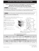
INSTALLATION AND SERVICE MUST BE PERFORMED BY A QUALIFIED INSTALLER.
IMPORTANT: SAVE FOR LOCAL ELECTRICAL INSPECTOR'S USE.
READ AND SAVE THESE INSTRUCTIONS FOR FUTURE REFERENCE.
FOR YOUR SAFETY:
Do not store or use gasoline or other flammable vapors and liquids in
the vicinity of this or any other appliance.
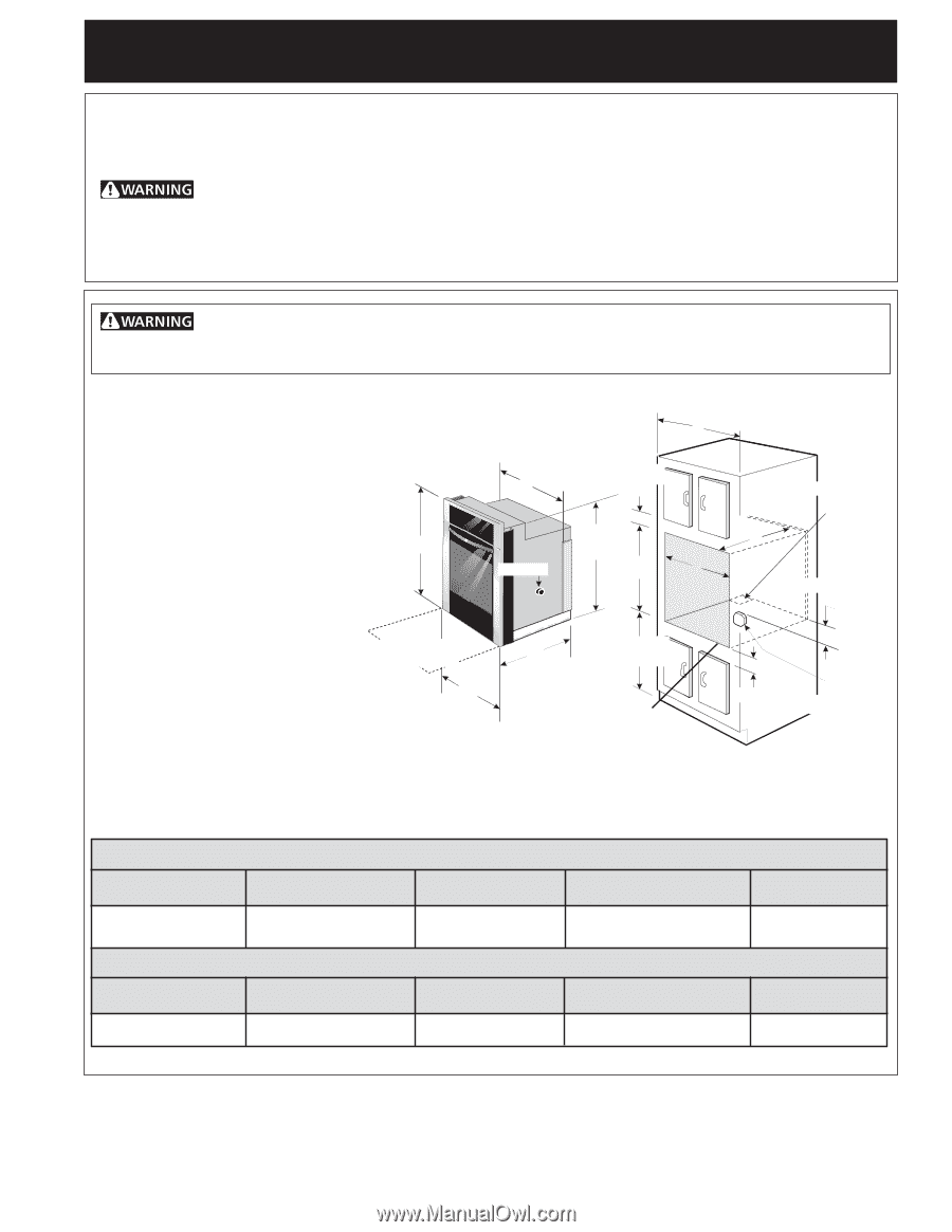
The first step of your installation should be to measure your current cutout dimensions and compare them
to the cutout dimensions chart below. You may find little or no cabinet work will be necessary.
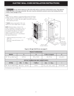
NOTE:
1. Base must be capable of supporting 200 pounds (90.7 kg).
2. Make sure base is level and front of cabinet is square. If the cabinet base
is not level, the oven glides will tend to slide out
when opening the door.
Figure 1 (Double Wall Oven see page 2)
P/N 318201524 (0709) Rev. C
English – pages 1-8
Español – páginas 9-16
Français – pages 17-24
All dimensions are in inches (cm).
Do not remove spacers on the side walls and/or on the back of the built-in oven. These
spacers center the oven in the space provided. The oven must be centered to prevent excess heat
buildup that may result in heat damage or fire.
PRODUCT DIMENSIONS
CUTOUT DIMENSIONS AND CABINET WIDTH
MODEL
30" (76.2 cm) Wall Oven
MODEL
30" (76.2 cm) Wall Oven
A
30 (76.2)
Min.
F
Max.
28
½
(72.4)
29 (73.7)
B
29
¼
(74.2)
G (Min.)
24 (61)
C (Rear wrapper)
28¼ (71.5)
Min.
H
Max
.
28¼ (71.8)
28
7
/
8
(73.3)
D
24
5
/
8
(62.5)
I
30 (76.2) Min
** NOTE:
Allow at least 23¼" (59.1 cm)
clearance for door depth when it is open.
NOTE:
Dimension
G
is critical to the proper
installation of the built-in oven.
If the oven
decorative moulding does not butt against
the cabinet, or if noise is heard on
convection models, verify dimension
G
to
assure it is according to the required
dimension.
*
Suggested distance from floor is 31"
(78.7 cm).
Minimum required distance is 4½" (11.4
cm).
NOTE:
For combination of this Built-in Oven with Warm &
Serve Drawer see cutout dimensions specified in the Warm &
Serve Drawer Installation Instructions.
Printed in United States
Bottom edge
must be finish-cut