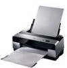
Epson 3800 Service Manual
Epson 3800 - Stylus Pro Color Inkjet Printer Manual
 |
UPC - 010343862081
View all Epson 3800 manuals
Add to My Manuals
Save this manual to your list of manuals |
Epson 3800 manual content summary:
- Epson 3800 | Service Manual - Page 1
SERVICE MANUAL Large Format Color Inkjet Printer EPSON Stylus Pro 3800/3800C/3850 SEIJ06007 - Epson 3800 | Service Manual - Page 2
, without the prior written permission of SEIKO EPSON CORPORATION. „ The contents of this manual are subject to change without notice. „ All effort have been made their respective owners. EPSON disclaims any and all rights in those marks. Copyright © 2006 SEIKO EPSON CORPORATION. Imaging Products - Epson 3800 | Service Manual - Page 3
3. WHEN PERFORMING TESTING AS DICTATED WITHIN THIS MANUAL, DO NOT CONNECT THE UNIT TO A POWER SOURCE UNTIL INSTRUCTED TO DO SO. WHEN THE POWER SUPPLY CABLE OTHER NON-APPROVED COMPONENTS MAY DAMAGE THE PRODUCT AND VOID ANY APPLICABLE EPSON WARRANTY. 6. WHEN AIR DUSTER IS USED ON THE REPAIR AND THE - Epson 3800 | Service Manual - Page 4
step-by-step procedures for the troubleshooting. CHAPTER 4.DISASSEMBLY / ASSEMBLY Describes the step-by-step procedures for disassembling and assembling the product. CHAPTER 5.ADJUSTMENT Provides Epson-approved methods for adjustment. CHAPTER 6.MAINTENANCE Provides preventive maintenance procedures - Epson 3800 | Service Manual - Page 5
Revision A Date of Issue November 30, 2006 First release Revision Status Description - Epson 3800 | Service Manual - Page 6
EPSON Stylus Pro 3800/3800C/3850 Contents Revision A Chapter 1 PRODUCT DESCRIPTION 1.1 Product Description 10 1.2 Basic Specifications 11 1.2.1 Basic Specifications 11 1.2.2 Electric Specifications 12 1.2.3 Environmental Characteristics 12 1.2.4 Reliability/Durability 13 1.3 Printing - Epson 3800 | Service Manual - Page 7
EPSON Stylus Pro 3800/3800C/3850 Chapter 4 DISASSEMBLY & ASSEMBLY 4.1 Overview ...86 4.1.1 Adjustment 237 5.3.20 PF Adjustment 239 5.3.21 EJ Adjustment 241 5.3.22 Check Ink Selector Operation 243 5.3.23 Write Constant When CR change 244 5.4 Check Results 245 5.4.1 Check Nozzle 245 5.4.2 Print - Epson 3800 | Service Manual - Page 8
EPSON Stylus Pro 3800/3800C/3850 Chapter 7 APPENDIX 7.1 Connectors ...263 7.2 Cables Connection Layout 265 7.3 ASP List ...267 7.4 Exploded Diagrams 269 7.5 Circuit Diagrams 278 Revision A 8 - Epson 3800 | Service Manual - Page 9
PRODUCT DESCRIPTION CHAPTER 1 - Epson 3800 | Service Manual - Page 10
EPSON Stylus Pro 3800/3800C/3850 1.1 Product Description EPSON Stylus Pro 3800/3800C/3850 are large size color inkjet printers that support up to A2 (17") sized cut-sheet paper. † F-Mach (180N x 8-column) print head † Maximum print resolution (dpi): 2880 x 1440, Minimum dot: 3.5pl MSDT † Superior - Epson 3800 | Service Manual - Page 11
EPSON Stylus Pro 3800/3800C/3850 Revision A 1.2 Basic Specifications 1.2.1 Basic Specifications Item Specifications Maximum paper width 17 inch (43 cm) Printing method On-demand ink jet method Printing direction Two-way shortest distance printing with logical seeking Type F-Mach Print - Epson 3800 | Service Manual - Page 12
EPSON Stylus Pro 3800 mA or less Compliance with regulations † Conforms to International Energy Star Program (Category: conforms to the harmonic restraint measure guideline) † Conforms to 80 32 60 55 Normal ambient environment 20 The printer allowable range 10 15 25 27 35 40 Temperature - Epson 3800 | Service Manual - Page 13
EPSON Stylus Pro 3800/3800C/3850 RESISTANCE TO VIBRATION/SHOCK Operating Storage Vibration 0.15G, 10 to 55Hz 0.50G, 10 to 55Hz Shock 1G, within 1ms 2G, within 2ms C A U T IO N „ When transporting the printer, the print head must be capped, and the ink cartridges must be removed. „ If the print - Epson 3800 | Service Manual - Page 14
inch) 25.4 mm (1 inch) when line feed: 333 msec (3 inch/sec) 1.3.2 Paper Feeder Specifications EPSON Stylus Pro 3800/3800C/3850 support three types of paper feeding methods; ASF, Rear Manual Feed, and Front Manual Feed. The paper size and thickness for each of the methods are shown in the table - Epson 3800 | Service Manual - Page 15
EPSON Stylus Pro 3800/3800C/3850 Revision A 1.3.3 Paper Support Media Name Premium Glossy Photo Paper Premium Semigloss Photo Paper Premium Luster Photo Paper Singleweight Matte Paper Photo Quality Ink Jet Paper (KANZAN for EU A4 only, ESF for others) Proofing Paper Semimatte (Commercial - Epson 3800 | Service Manual - Page 16
EPSON Stylus Pro 3800/3800C/3850 1.3.4 Printable Area Item Dimension LM PW (paper width) 89mm to 431.8mm PL (paper length) 127mm to 950mm TM (top margin) 0mm/3mm/20mm* BM (bottom margin) 0mm/3mm/20mm* LM (left margin) 0mm/3mm RM (right margin) 0mm/ - Epson 3800 | Service Manual - Page 17
EPSON Stylus Pro 3800/3800C/3850 Revision A 1.4 Print Mode This section provides specifications of the print mode and borderless printing. 1.4.1 Print Mode Media Type Print Quality Print Density (H x V) Draft Plain Paper Normal (360 dpi) 360 x 360 dpi 720 x 360 dpi Normal (360 dpi) 720 x - Epson 3800 | Service Manual - Page 18
EPSON Stylus Pro 3800/3800C/3850 Revision A AUTOMATIC EXPANSION SPECIFICATION The driver automatically changes margins that bleed off the edges of paper according to the paper size. Table 1-6. Borderless Printing Margins (Bleed) Top Left/Right Bottom L/4" x 6" 16:9 Wide 5" x 7" 8" x 10" A4 / - Epson 3800 | Service Manual - Page 19
EPSON Stylus Pro 3800/3800C/3850 1.5 ink cartridges) 1.5.2 Part Names Paper Support Auto Sheet Feeder Edge Guide Top Cover Ink Cover Paper Support Edge Guide Paper Eject Tray Paper Eject Tray Cover Rear Paper Feeder Print Head (Nozzle) Operation Panel Maintenance Cartridge Cover Board Paper - Epson 3800 | Service Manual - Page 20
EPSON Stylus Pro 3800/3800C/3850 Revision A 1.6 Operation Panel 1.6.1 Buttons and Functions A Power LED B Paper status LED C Ink status LED 1 Back/Left 2 Ink Cover Open/Up 3 Power 4 Cancel/Reset 1.6.2 Buttons 5 Enter 6 Paper Feed/Down Figure 1-7. Operation Panel 7 Menu/Right Button 1 Power - Epson 3800 | Service Manual - Page 21
EPSON Stylus Pro 3800/3800C/3850 1.6.4 Panel Display † Normal indication † Error indication 2 Revision A 1 1 2 6 34 5 Figure 1-8. Panel Display (Normal indication) No. Item Description 1 Messages Printer status, operation status, and error messages are displayed. 2 User-defined paper No - Epson 3800 | Service Manual - Page 22
EPSON Stylus Pro 3800/3800C/3850 1.6.5 Icons on the LCD PLATEN GAP SETTING The platen gap specified in PRINTER SETUP and CUSTOM PAPER menus is indicated with icons as shown below. Icons -- Status STANDARD is selected. NARROW is selected. WIDE is selected. WIDER is selected. WIDEST is - Epson 3800 | Service Manual - Page 23
EPSON Stylus Pro 3800/3800C/3850 MAINTENANCE CARTRIDGE STATUS † Maintenance Cartridge Counter The free space of the Maintenance Cartridge is indicated as shown below. Figure 1-12. Maintenance Cartridge Status Table 1-8. Relation between Counters and Remaining Ink No. Free Space (%) No. Free - Epson 3800 | Service Manual - Page 24
EPSON Stylus Pro 3800/3800C/3850 1.6.6 Menu Settings Top Menu Menu Items PRINTER SETUP TEST PRINT PRINTER STATUS PLATEN GAP PAPER SIZE CHECK INITIALIZE SETTINGS NOZZLE CHECK STATUS SHEET NETWORK STATUS SHEET JOB INFORMATION CUSTOM PAPER VERSION PRINTABLE PAGES INK LEVEL MAINTENANCE TANK USAGE - Epson 3800 | Service Manual - Page 25
EPSON Stylus Pro 3800/3800C/3850 Top Menu Menu Items PAPER NUMBER (1-10) PAPER TYPE CUSTOM PAPER PLATEN GAP MAINTENANCE THICKNESS PATTERN PAPER FEED ADJUST A PAPER FEED ADJUST B DRYING TIME BLACK INK CHANGE POWER CLEANING CLOCK SETTING CONTRAST ADJUSTMENT AUTO HEAD ALIGNMENT MANUAL - Epson 3800 | Service Manual - Page 26
EPSON Stylus Pro 3800/3800C/3850 Top Menu Menu Items NETWORK SETUP NETWORK SETUP IP ADDRESS items appear only when ENABLE has been selected. Under the following conditions, this setting is automatically changed to DISABLE. • Every power-on (always returns to the default: DISABLE) • When the - Epson 3800 | Service Manual - Page 27
EPSON Stylus Pro 3800/3800C/3850 † PG settings list The table below lists the platen gap amounts settable with the printer driver, control panel, and media table. Printer Driver Paper Thickness setting No setting 0.0 to 0.8mm 0.9mm to 1.5mm Table 1-10. PG Setting List Control Panel Setting - Epson 3800 | Service Manual - Page 28
EPSON Stylus Pro 3800/3800C/3850 1.6.7 Maintenance Mode HOW TO START & QUIT † Starting Method Turn the printer On while holding down the Cancel/Reset button. † Quitting Method Turn the printer to their default. „ PRINTER SETUP menu „ PRINTER STATUS menu „ CUSTOM PAPER menu „ HEAD ALIGNMENT menu - Epson 3800 | Service Manual - Page 29
JAMMED PAPER SEE PRINTER GUIDE FOR INSTRUCTIONS -- PLEASE WAIT -- UPDATING FIRMWARE -- RESETTING PLEASE WAIT NO MAINTENANCE CART. INSTALL THE MAINTENANCE CARTRIDGE. MAINTENANCE COVER OPEN CLOSE THE MAINTENANCE COVER PAPER FEED ERROR REMOVE PAPER -- AND LOAD PAPER CORRECTLY PAPER FEED - Epson 3800 | Service Manual - Page 30
EPSON Stylus Pro 3800/3800C/3850 No Error/Warning Status 13 Paper Jam Discharge Failed Remove Paper 14 Waiting Cartridge Cover open 15 Cartridge Cover Cannot Be Opened 16 Detecting Ink Cartridge (Cover close -> READY) 17 Maintenance Cartridge Insufficient 18 Ink Cartridge Insufficient 19 - Epson 3800 | Service Manual - Page 31
EPSON Stylus Pro 3800/3800C/3850 No Error/Warning Status 24 Board paper removal error Board Paper Tray Open Error 25 The tray was opened during operation Board tray open error 26 Set paper Board Tray Close Error 27 The tray was opened during operation Board Tray Close Error 28 Paper needs to be - Epson 3800 | Service Manual - Page 32
EPSON Stylus Pro 3800/3800C/3850 No Error/Warning Status 35 Ink Cover Open 36 Ink Initial Refilling 37 K Ink Changing 38 Cleaning 39 Command Error 40 Paper Skew Error 41 Paper Identification Error (PW Inspection) 42 Borderless Printing Error Paper Discharge Failed Error (Cut Sheet Paper) 43 - Epson 3800 | Service Manual - Page 33
EPSON Stylus Pro 3800/3800C/3850 No Error/Warning Status 47 Paper Size Check Error 48 Ink Mark Sensor Sensitivity Control Error Ink Mark Sensor Adjusted Value Error 49 Adjusted value cannot be set Adjusted range over Nozzle Check Error 50 Nozzle cannot be recovered Cleaning Error 51 W/ board - Epson 3800 | Service Manual - Page 34
EPSON Stylus Pro 3800/3800C/3850 No Error/Warning Status 63 Maintenance Cartridge Cover Open Warning 64 Maintenance Cartridge Low 65 Printing 66 Analyzing 67 Printable (Idling) Error or Illustration Warning on LCD Message on LCD Warning Warning ---- MAINTENANCE COVER OPEN CLOSE THE - Epson 3800 | Service Manual - Page 35
OPERATING PRINCIPLES CHAPTER 2 - Epson 3800 | Service Manual - Page 36
EPSON Stylus Pro 3800/3800C/3850 2.1 Overview OPERATING PRINCIPLES OVERVIEW 2.6 Paper Feed Mechanism Explains how paper is fed and transported. • PF Motor • ASF • PE Sensor • Paper Eject Tray 2.3 Ink Supply Mechanism Explains how the ink is supplied from the cartridges to the print - Epson 3800 | Service Manual - Page 37
EPSON Stylus Pro 3800/3800C/3850 MAIN COMPONENT † Electric Circuit Boards Table 2-1. List of Indicates printer status by the LED. Relays connections between the main board and the following parts: † PG sensor † Ink mark sensor † PW sensor † Ink change sensor † CR encoder † Ink change motor - Epson 3800 | Service Manual - Page 38
EPSON Stylus Pro 3800/3800C/3850 † Motors/Solenoid Table 2-2. List of Motors/Solenoid Fig. Name 1 Release motor Driven Parts Specifications Release roller Type: DC motor Voltage:42 VDC ± 5 % 2 PF motor 3 Ink cover unlock solenoid 4 Pressure pump motor 5 Ink change motor 6 Pump motor 7 CR - Epson 3800 | Service Manual - Page 39
EPSON Stylus Pro 3800/3800C/3850 Revision A † Sensors/ black ink switch lever. Voltage: 3.3 VDC ± 5 % 11 Ink mark sensor † Auto Bi-D adjustment Type: Diffuse reflective photo interrupter † Auto Uni-D adjustment Voltage: 3.3 VDC ± 5 %, LED: 5 V † Auto nozzle check 12 Maintenance cartridge cover - Epson 3800 | Service Manual - Page 40
EPSON Stylus Pro 3800/3800C/3850 Revision A 2.2 Print Mechanism This section explains the basic specifications of the print head. NOZZLE CONFIGURATION AND COLORS This printer is equipped with an MACH print head, which employs 180 nozzles per color. The printer ejects nine different colors of ink - Epson 3800 | Service Manual - Page 41
EPSON Stylus Pro 3800/3800C/3850 2.3 Ink Supply Mechanism 2.3.1 Ink Flow Path The ink flow path is shown below. Revision A 2.3.2 Ink Pressurizing Mechanism This printer employs an ink pressurizing mechanism to stably supply ink in the ink cartridge (ink pack) to the print head. This ink - Epson 3800 | Service Manual - Page 42
EPSON Stylus Pro 3800/3800C/3850 2.3.2.1 Pressure Pump Unit Mechanism † Accordion unit/Pressure pump motor/Pressure pump home sensor The accordion unit intakes air and applies pressure by the rotating drive of the pressure pump motor, and pumps air into the ink cartridges. The pressure pump home - Epson 3800 | Service Manual - Page 43
EPSON Stylus Pro 3800/3800C/3850 2.3.3 Ink Change System This printer has automatic ink change system that switches black ink between Photo Black and Matte Black. The cartridge holder of this printer keeps both Photo Black and Matte Black ink cartridges. Each of the black ink cartridges has its own - Epson 3800 | Service Manual - Page 44
EPSON Stylus Pro 3800/3800C/3850 Revision A 2.4 Cleaning Mechanism The cleaning mechanism consists of a pump cap unit and a waste ink pads (maintenance cartridge up and down. The cap unit goes up to seal the print head during cleaning and stand-by. Carriage lock operates in synchronization with - Epson 3800 | Service Manual - Page 45
EPSON Stylus Pro 3800/3800C/3850 † Pump Unit The ink is absorbed from the head nozzles. The sucked waste ink is conveyed to the waste ink pad through the tube. The CW rotation of the pump motor rotates the conveyance roller. The roller rotates pressing the tube to convey the waste ink from the cap - Epson 3800 | Service Manual - Page 46
EPSON Stylus Pro 3800/3800C/3850 2.5 Carriage Mechanism The carriage mechanism consists of a carriage movement mechanism, platen gap adjustment timing belt, and the carriage unit moves left and right along the carriage guide shaft. The CR encoder installed on the back of the carriage unit reads - Epson 3800 | Service Manual - Page 47
EPSON Stylus Pro 3800/3800C/3850 2.5.2 Platen Gap Adjustment Mechanism Platen gap adjustment mechanism consists of an APG motor, carriage unit, and PG sensor. The carriage unit is equipped with two carriages; main carriage that moves horizontally to the carriage guide shaft, and the sub carriage - Epson 3800 | Service Manual - Page 48
EPSON Stylus Pro 3800/3800C/3850 2.6 Paper Feed Mechanism 2.6.1 Paper Feed Path The printer provides two manual paper feed paths in addition to the ASF to support thicker paper. Paper Feeding 1 ASF (Auto Sheet Feeder) 2 Rear Manual Bypass 3 Front Manual Bypass Thickness 0.08 to 0.27 mm 0.29 to - Epson 3800 | Service Manual - Page 49
EPSON Stylus Pro 3800/3800C/3850 Revision A 2.6.2 Paper Loading Mechanism ASF (AUTO SHEET FEEDER) The ASF, whose driving source is an ASF motor, consists of a LD roller, LD roller shaft, ASF sensor, hopper, and paper anti-slip tab. The cams on both ends of the LD roller shaft activate the hopper - Epson 3800 | Service Manual - Page 50
EPSON Stylus Pro 3800/3800C/3850 Revision A 4. Pressing the hopper The hopper cam on the LD roller shaft presses the hopper and remaining paper on the tray is moved away from the feeding position. 5. Moving the paper anti-slip tabs upward The LD roller shaft rotates to actuate the lever on the - Epson 3800 | Service Manual - Page 51
EPSON Stylus Pro 3800/3800C/3850 REAR MANUAL BYPASS When the prescribed time has passed since a paper was supplied from the feeder on the rear of the printer and the PE sensor detected the paper, the PF roller starts to transport the paper. FRONT MANUAL BYPASS The status of the board paper tray that - Epson 3800 | Service Manual - Page 52
EPSON Stylus Pro 3800/3800C/3850 2.6.3 Paper Feed Mechanism The paper feed mechanism mainly consists of a Release mechanism, the PF Motor, and the feed rollers. RELEASE MECHANISM Release mechanism consists of a release unit (including a release motor, release sensor, and combination gear), paper - Epson 3800 | Service Manual - Page 53
EPSON Stylus Pro 3800/3800C/3850 Spur Gear, 22 Combination Gear, 9.6, 22 Combination Gear, 8, 22.986 Release Motor Combination Gear, 8, 22 Paper Guide Release Shaft Spur Gear, 20.4 Release Sensor Light-shielding Plate Combination Gear, 22, 32.4 Spur Gear, 22,B OPERATING PRINCIPLES Paper Guide - Epson 3800 | Service Manual - Page 54
EPSON Stylus Pro 3800/3800C/3850 PAPER FEED MECHANISM Paper feed mechanism consists of a PF motor, PF scale, PF encoder, PF roller, front and rear paper eject rollers, and star wheels. The mechanism transports papers fed from the feeders and ejects them from the front of the printer. PF Motor PF - Epson 3800 | Service Manual - Page 55
EPSON Stylus Pro 3800/3800C/3850 Frame, EJ Assy Paper Revision A PF Roller Star Wheel Front Paper Eject Roller Rear Paper Eject Roller Spur Gear, 14.4 PF Encoder Spur Gear, 68 OPERATING PRINCIPLES PF Motor PF Timing Belt Figure 2-30. Paper Feed Mechanism Paper Feed Mechanism Spur Gear, 31 - Epson 3800 | Service Manual - Page 56
EPSON Stylus Pro 3800/3800C/3850 2.7 Ink Mark Sensor This printer is equipped with the ink mark sensor functioning as multi sensors. The sensor, located on the bottom of the carriage unit, is a diffuse reflective photointerruptor that is comprised of a light emitting - Epson 3800 | Service Manual - Page 57
EPSON Stylus Pro 3800/3800C/3850 Revision A 2.8 Other Mechanisms INK COVER OPEN-CLOSE MECHANISM To keep the ink cartridges from being removed during printing, opening/closing of the ink cover is electrically regulated. Opening/closing of the cover is controlled by the lock mechanism that takes - Epson 3800 | Service Manual - Page 58
EPSON Stylus Pro 3800/3800C/3850 2.9 Outline of Circuit Boards 2.9.1 Main Board This section provides a summary of the main board (C653MAIN) that controls the whole of the printer system. † Explanation of main elements on C635 MAIN Board Model Number E01A68CB FlashROM DDR-SDRAM RTC9824 E09A54RA - Epson 3800 | Service Manual - Page 59
EPSON Stylus Pro 3800/3800C/3850 2.9.2 Power Supply Board This section describes the power supply board that generates the power to operate this printer. CIRCUIT BLOCK DIAGRAM The block diagram of C635 Power Supply board is shown below. AC input Input Filter (Rush current prevention circuit - Epson 3800 | Service Manual - Page 60
EPSON Stylus Pro 3800/3800C/3850 2.10 Colorimetric Calibration (Color ID) Overview This printer employs "Colorimetric Calibration (Color ID)" to correct unit-to-unit variations in color. Colorimetric Calibration (Color ID) corrects not only the weight of ink droplets which differs depending on the - Epson 3800 | Service Manual - Page 61
TROUBLE SHOOTING CHAPTER 3 - Epson 3800 | Service Manual - Page 62
EPSON Stylus Pro 3800/3800C/3850 3.1 Overview This section explains the basic procedure for troubleshooting problems on the printer quickly and efficiently. 3.1.1 Preliminary Check Make sure to verify or perform the following basic items whenever servicing the printer. 1. There is no foreign - Epson 3800 | Service Manual - Page 63
THE CARRIAGE LOCK PAPER JAM CLEAR JAMMED PAPER SEE PRINTER GUIDE FOR INSTRUCTIONS NO MAINTENANCE CART. INSTALL THE MAINTENANCE CARTRIDGE. MAINTENANCE COVER OPEN CLOSE THE MAINTENANCE COVER PAPER FEED ERROR REMOVE PAPER AND LOAD PAPER CORRECTLY Description Maintenance Call Warning Ink level is low - Epson 3800 | Service Manual - Page 64
> INK CARTRIDGE REPLACE INK CARTRIDGE INK COVER OPEN CLOSE THE INK COVER COMMAND ERROR CHECK DRIVER SETTINGS PAPER SKEW PRESS THE DOWN BUTTON LOAD PAPER CORRECTLY PAPER ERROR PRESS THE DOWN BUTTON LOAD PAPER CORRECTLY BORDERLESS ERROR PRESS THE DOWN BUTTON LOAD THE CORRECT SIZE PAPER PAPER - Epson 3800 | Service Manual - Page 65
PRESS THE DOWN BUTTON AND REMOVE THICK PAPER PAPER SETTING ERROR CHECK PAPER SOURCE IN THE DRIVER SETTINGS AND LOAD PAPER CORRECTLY No paper is detected. The size of loaded paper does not match with the paper size setting. The ink mark sensor sensitivity adjustment could not be made. Failed to - Epson 3800 | Service Manual - Page 66
EPSON Stylus Pro 3800/3800C/3850 Revision A 3.3 Remedies for Warning Messages When a Warning error occurs, the printer displays a Warning message instead of "READY" or "PRINTING" messages, however, it does not interfere with printing operation. REMEDIES The following tables explains the Warning - Epson 3800 | Service Manual - Page 67
The counter of waste ink used for printing margins at borderless printing has reached the specified value. Replace the waste ink pads for borderless printing (POROUS PAD,INK WASTE BOX, LEFT/RIGHT) with new ones, and clear the counter using the Adjustment Program. 0 1 (NA) 0 (NA) (NA) 0 0 0 (NA - Epson 3800 | Service Manual - Page 68
EPSON Stylus Pro 3800/3800C/3850 Revision A 3.4 Remedies for Error Messages The following tables explains the error messages and remedies. Message on LCD SERVICE CALL ERROR NNNN PLEASE CONTACT TO THE REPAIR CENTER PRINTER ERROR RESTART THE PRINTER CARRIAGE LOCKED RELEASE THE CARRIAGE LOCK PAPER - Epson 3800 | Service Manual - Page 69
EPSON Stylus Pro 3800/3800C/3850 Revision A Message on LCD PAPER FEED ERROR LOAD PAPER CORRECTLY AND PRESS PAPER/FEED BUTTON PAPER JAM REMOVE PAPER CANNOT OPEN COVER IS THERE ANYTHING ON THE PRINTER? PRESS THE UP BUTTON MAINTENANCE CARTRIDGE NEARLY FULL REPLACE THE CARTRIDGE NOT ENOUGH INK - Epson 3800 | Service Manual - Page 70
EPSON Stylus Pro 3800/3800C/3850 Revision A Message on LCD FRONT FEED SLOT OPEN PRESS THE DOWN BUTTON AND REMOVE PAPER FRONT FEED SLOT OPEN CLOSE THE FRONT MANUAL FEED SLOT FRONT FEED SLOT OPEN LOAD MEDIA AND PRESS THE DOWN BUTTON FRONT SLOT CLOSED OPEN THE FRONT MANUAL FEED SLOT FRONT SLOT CLOSED - Epson 3800 | Service Manual - Page 71
Stylus Pro 3800/3800C/3850 Revision A Message on LCD INK CARTRIDGE NON-GENUINE CARTRIDGE! MAY NOT PERFORM AT OPTIMUM. CONTINUE? INK CARTRIDGE THIS MAY VOID EPSON'S WARRANTY. DO YOU ACCEPT THIS? INK CARTRIDGE REPLACE INK CARTRIDGE INK COVER OPEN CLOSE THE INK - Epson 3800 | Service Manual - Page 72
EPSON Stylus Pro 3800/3800C/3850 Revision A Message on LCD BORDERLESS ERROR PRESS THE DOWN BUTTON LOAD THE CORRECT SIZE PAPER PAPER EJECT ERROR PRESS THE DOWN BUTTON AND REMOVE PAPER PAPER FEED ERROR LOAD PAPER CORRECTLY PRESS THE DOWN BUTTON PAPER REMOVE REMOVE PAPER FROM THE REAR PAPER ERROR - Epson 3800 | Service Manual - Page 73
EPSON Stylus Pro 3800/3800C/3850 Revision A Message on LCD PAPER SENSOR ERROR PRESS THE BUTTON LOAD THE CORRECT PAPER CLEANING ERROR PRESS THE CANCEL/RESET BUTTON CLEANING ERROR PRESS THE DOWN BUTTON AND REMOVE THICK PAPER PAPER SETTING ERROR CHECK PAPER SOURCE IN THE DRIVER SETTINGS AND LOAD - Epson 3800 | Service Manual - Page 74
EPSON Stylus Pro 3800/3800C/3850 Revision A 3.5 Remedies for Service Call Error The following tables explains the Service Call error messages and remedies. CHECK P O IN T Make sure to check the related connectors and cables for poor connection or any abnormality before replacing any - Epson 3800 | Service Manual - Page 75
EPSON Stylus Pro 3800/3800C/3850 Revision counter using the Adjustment Program. The carriage unit cannot be unlocked. See 4.3.9.1 PUMP, CAP ASSY. on page 148. CR lock set error The printer cannot lock the MOTOR ASSY., CR on page 121. TROUBLE SHOOTING Remedies for Service Call Error 75 - Epson 3800 | Service Manual - Page 76
EPSON Stylus Pro 3800/3800C/3850 Revision A Error Code 1134 1135 1221 1222 1220 1223 1224 Error Name Integral term overload (PID-load if not proper. Replace the PF motor (MOTOR, RELEASE, ASSY). See 4.3.10.3 MOTOR, RELEASE, ASSY. on page 167. TROUBLE SHOOTING Remedies for Service Call Error 76 - Epson 3800 | Service Manual - Page 77
the ink cartridge. Air is leaking through a gap between the ink cartridge and the ink Check junction of the ink cartridge and the ink cartridge holder, cartridge holder due to an obstruction between them. and remove any obstruction between them if any. TROUBLE SHOOTING Remedies for Service Call - Epson 3800 | Service Manual - Page 78
EPSON Stylus Pro 3800/3800C/3850 Revision A Error Code Error Name 1410 Drive time monitor time-out (PUMP) 142D Pump cap unit life error 1425 CSIC communication time-out 1430 Holder ink pad error 1431 Ink selector error 1432 Ink selector drive timeover 1434 Ink cover unlock error - Epson 3800 | Service Manual - Page 79
EPSON Stylus Pro 3800/3800C/3850 Error Code Error Name 150C PF phase detection error 1511 Drive time monitor time-out (APG) 1520 Drive time monitor time-out (CR) 1531 ASF phase detection error 1535 Pressure pump home detection error 1550 Borderless print ink pad error 1600 Paper - Epson 3800 | Service Manual - Page 80
EPSON Stylus Pro 3800 head temperature fell outside the Replace the print head. specified range. See 4.3.9.5 PRINT HEAD on page 159. The head thermistor socket on the power supply board failure, or main board failure. printer) for poor connection or breaks. Replace the power supply board (BOARD - Epson 3800 | Service Manual - Page 81
EPSON Stylus Pro 3800/3800C/3850 Error Code Error Name DXXX Error code for debugging FXXX CPU-related error Description . Replace the main board (BOARD ASSY., MAIN). See 4.3.4.1 BOARD ASSY., MAIN on page 112. Install a normal firmware. TROUBLE SHOOTING Remedies for Service Call Error 81 - Epson 3800 | Service Manual - Page 82
EPSON Stylus Pro 3800/3800C/3850 Revision A 3.6 Remedies for Print Quality Troubles This section provides troubleshooting of print quality troubles classifying them by observed symptom. Symptom Dot missing Description The nozzles are clogging with ink. Ink cannot be fired normally due to a - Epson 3800 | Service Manual - Page 83
EPSON Stylus Pro 3800/3800C/3850 Symptom Ink smear (backside) Description Paper is curled or creased. The paper is contaminated by ink smear in the paper feed path. Horizontal banding The waste ink pads for borderless printing are not securely attached and contaminating paper. Paper setting made - Epson 3800 | Service Manual - Page 84
EPSON Stylus Pro 3800/3800C/3850 Symptom Vertical banding (overall) Description Bi-D and Uni-D adjustments have not been carried out properly. The carriage unit cannot move smoothly. Remedy Carry out the Auto Bi-D and the Auto Uni-D adjustments. See Chapter 5 "ADJUSTMENT". Check the CR timing - Epson 3800 | Service Manual - Page 85
DISASSEMBLY & ASSEMBLY CHAPTER 4 - Epson 3800 | Service Manual - Page 86
EPSON Stylus Pro 3800 ADJUSTMENT REQUIRED". Be sure to perform the specified adjustments with reference to Chapter 5 "ADJUSTMENT instructions cover the printer ink gets in your eye, flush the eye with fresh water and see a doctor immediately. „ Never touch the ink or wasted ink with bare hands. If ink - Epson 3800 | Service Manual - Page 87
EPSON Stylus Pro 3800/3800C/3850 Revision A C A U T IO N „ Ensure sufficient work space for servicing. „ Locate the printer on a stable and flat surface. „ The ink-path-related components or parts should be firmly and securely installed on the printer to prevent ink from leakage. „ Use only - Epson 3800 | Service Manual - Page 88
EPSON Stylus Pro 3800/3800C/3850 4.1.2 Orientation Definition The following figure defines the orientation of the printer, which is applicable to chapter 4. Up Left Front Rear Right Revision A 4.1.3 Tools To protect the printer from damage, use the tools indicated in the following table. Name - Epson 3800 | Service Manual - Page 89
EPSON Stylus Pro 3800/3800C/3850 4.1.4 Screws The following table indicates the screws used in the printer. Name Protective Screw C.B.P. 3x8 C.B.S. 3x8 C.B.P. 3x6 C.B.S. 3x6 C.F.S. on-site and off-site services „ Group 2: Applicable to off-site service only. DISASSEMBLY & ASSEMBLY Overview 89 - Epson 3800 | Service Manual - Page 90
EPSON Stylus Pro 3800/3800C/3850 Revision A 4.2 Disassembly Flowchart Start Parts shown in the dotted-line boxes are not the shortest procedures to remove them, but are necessary to proceed to the next step. COVER, IH, ASSY. (p94) HOUSING, REAR, ASSY. (p95) COVER, HOUSING, LOWER (p107) SCALE, - Epson 3800 | Service Manual - Page 91
EPSON Stylus Pro 3800/3800C/3850 4.3 Disassembly/Assembly Procedure (Group 1) This section describes disassembly/assembly procedures required for both on-site and off-site servicing. 4.3.1 Unlocking the CARRIAGE, ASSY. manually 1. Remove the HOUSING, RIGHT. (p103) 2. While pressing the carriage lock - Epson 3800 | Service Manual - Page 92
EPSON Stylus Pro 3800/3800C/3850 4.3.2 Consumable 4.3.2.1 Ink Cartridge 1. Turn the printer ON. 2. Hold down the Ink Cover Open/Up button on the operation panel for more than three seconds. The COVER, IH, ASSY. will be unlocked and slightly opened. 3. Open the COVER, IH, ASSY. 4. Press the Ink - Epson 3800 | Service Manual - Page 93
EPSON Stylus Pro 3800/3800C/3850 4.3.2.2 Maintenance Cartridge 1. Open the COVER, WB. 2. Slightly lift the Maintenance Cartridge and pull it out from the main unit. C A U T IO N Never touch the IC chip on the Maintenance Cartridge. Doing so may cause a detection error of the Maintenance Cartridge - Epson 3800 | Service Manual - Page 94
EPSON Stylus Pro 3800/3800C/3850 4.3.3 Removing the Housing and OPERATION, PANEL, ASSY. 4.3.3.1 COVER, IH, ASSY. C A U T IO N As the COVER, IH, ASSY is locked by the electric system, be sure to open the COVER, IH, ASSY. with the power turned on. Never force the COVER, IH, ASSY. open, or the lock - Epson 3800 | Service Manual - Page 95
EPSON Stylus Pro 3800/3800C/3850 4.3.3.2 HOUSING, REAR, ASSY. 1. Remove the five screws that secure the HOUSING, REAR, ASSY. and remove it. „ Four C.B.P. 3 x 6 screws (6 ± 1 kgf.cm) „ One C.B.S. 3 x 8 screw (6 ± 1 kgf. - Epson 3800 | Service Manual - Page 96
EPSON Stylus Pro 3800/3800C/3850 Install the HOUSING, REAR, ASSY. so that all the positioning hook F Left rear side One positioning hook HOUSING, REAR, ASSY. Two guide pins One positioning tab Two guide pins One positioning tab One positioning tab One positioning tab B Revision A D HOUSING - Epson 3800 | Service Manual - Page 97
EPSON Stylus Pro 3800/3800C/3850 4.3.3.3 HOUSING, FRONT, LEFT 1. Open the STACKER, C. 2. Remove the screw that secures the HOUSING, FRONT, LEFT to the main unit. „ One C.B.P. 3 x 8 screw (6 ± 1 kgf.cm) 3. - Epson 3800 | Service Manual - Page 98
EPSON Stylus Pro 3800/3800C/3850 4.3.3.4 HOUSING, FRONT, RIGHT 1. Open the STACKER, C. 2. Remove the screw that secures the HOUSING, FRONT, RIGHT to the main unit. „ One C.B.P. 3 x 8 screw (6 ± 1 kgf.cm) 3. - Epson 3800 | Service Manual - Page 99
EPSON Stylus Pro 3800/3800C/3850 4.3.3.5 COVER, PRINTER 1. Open the COVER, PRINTER. 2. Widen the parts shown in Figure 4-11 to release the COVER, PRINTER from the two bosses (left and right), and remove the COVER, PRINTER. Revision A COVER, PRINTER Figure 4-11. Removing the COVER, PRINTER - Epson 3800 | Service Manual - Page 100
EPSON Stylus Pro 3800/3800C/3850 4.3.3.6 PAPER, SUPPORT, MANUAL, ASSY. 1. Remove the PAPER, SUPPORT, MANUAL, ASSY. upward. Be sure to engage all the hooks (two on the upper part , five on the lower part ) of the PAPER, SUPPORT, MANUAL, ASSY. with the main unit. Revision A PAPER, SUPPORT, MANUAL, - Epson 3800 | Service Manual - Page 101
EPSON Stylus Pro 3800/3800C/3850 4.3.3.7 PAPER, SUPPORT, ASSY. 1. Open the PAPER, SUPPORT, ASSY. 2. Push on the circled points of the PAPER, SUPPORT, ASSY. inward to release its both pivots, and remove the PAPER, SUPPORT, ASSY. Revision A PAPER, SUPPORT ASSY. Figure 4-13. Removing the PAPER - Epson 3800 | Service Manual - Page 102
EPSON Stylus Pro 3800/3800C/3850 4.3.3.8 HOUSING, LEFT A C A U T I O N Do not remove or install the HOUSING, LEFT roughly, or the hooks and the tabs on the HOUSING, LEFT may be - Epson 3800 | Service Manual - Page 103
EPSON Stylus Pro 3800/3800C/3850 4.3.3.9 HOUSING, RIGHT A C A U T I O N Do not remove or install the HOUSING, RIGHT roughly, or the hooks and the tabs on the HOUSING, RIGHT may be - Epson 3800 | Service Manual - Page 104
EPSON Stylus Pro 3800/3800C/3850 4.3.3.10 HOUSING, FRONT, UPPER 1. Remove the HOUSING, REAR, ASSY. (p95) 2. Remove the HOUSING, FRONT, LEFT. (p97) 3. Remove the HOUSING, FRONT, RIGHT. (p98) 4. Remove the COVER, PRINTER. (p99) 5. Remove the HOUSING, LEFT. (p102) 6. Remove the HOUSING, RIGHT. (p103) - Epson 3800 | Service Manual - Page 105
EPSON Stylus Pro 3800/3800C/3850 4.3.3.11 OPERATION, PANEL, ASSY. 1. Remove the HOUSING, REAR, ASSY. (p95) 2. Remove the HOUSING, FRONT, RIGHT. (p98) 3. Remove the HOUSING, RIGHT. (p103) 4. Release the - Epson 3800 | Service Manual - Page 106
EPSON Stylus Pro 3800/3800C/3850 4.3.3.12 HOUSING, UPPER 1. Remove the HOUSING, REAR, ASSY. (p95) 2. Remove the HOUSING, FRONT, LEFT. (p97) 3. Remove the HOUSING, FRONT, RIGHT. (p98) 4. Remove the COVER, PRINTER. (p99) 5. Remove the HOUSING, LEFT. (p102) 6. Remove the HOUSING, RIGHT. (p103) 7. - Epson 3800 | Service Manual - Page 107
EPSON Stylus Pro 3800/3800C/3850 4.3.3.13 COVER, HOUSING, LOWER 1. Remove the HOUSING, UPPER. (p106) 2. Pull the upper part of the COVER, HOUSING, LOWER rightward and remove the COVER, HOUSING, LOWER upward while avoiding the FFCs on the main unit. Right side of the printer Revision A FFC COVER, - Epson 3800 | Service Manual - Page 108
EPSON Stylus Pro 3800/3800C/3850 4.3.3.14 Disassembling the OPERATION, PANEL, ASSY. 1. Remove the OPERATION , ASSY. „ When installing the SHIED PLATE, be sure to insert its two positioning holes over the guide pins on the OPERATION BUTTON. See Figure 4-21. „ When installing the BOARD ASSY. PANEL, be - Epson 3800 | Service Manual - Page 109
EPSON Stylus Pro 3800/3800C/3850 4. Remove the OPTICAL TUBE, LED, LEFT/RIGHT and the BUTTON, PS from the OPERATION PANEL. See Figure 4-23. 5. Remove the OPERATION BUTTON from the OPERATION PANEL. See Figure 4-23. 6. Remove the COVER, LCD secured to the OPERATION PANEL with the twosided tape. See - Epson 3800 | Service Manual - Page 110
EPSON Stylus Pro 3800/3800C/3850 4.3.3.15 BASE, ENCLOSURE 1. Remove the HOUSING, REAR, ASSY. (p95) 2. Remove the HOUSING, FRONT, LEFT. (p97) 3. Remove the HOUSING, FRONT, RIGHT. (p98) 4. remove the COVER, PRINTER. (p99) 5. Remove the HOUSING, LEFT. (p102) 6. Remove the HOUSING, RIGHT. (p103) 7. - Epson 3800 | Service Manual - Page 111
EPSON Stylus Pro 3800/3800C/3850 10. Remove the four screws that secure the BASE, ENCLOSURE to the main unit. See Figure unit to avoid damaging the cables. 11. Pull out the BASE, ENCLOSURE from the back of the printer. See Figure 4-28. C A U T IO N Do not disconnect/insert the FFCs from/into - Epson 3800 | Service Manual - Page 112
EPSON Stylus Pro 3800/3800C/3850 4.3.4 Removing the Circuit Boards 4.3.4.1 BOARD ASSY., MAIN 1. Pull out the BASE . Connect the FFCs to their correct positions matching the numbers written on the FFCs with those printed on the board as shown in Figure 4-29 and Table 4-3. Revision A CN30 CN49 CN76 - Epson 3800 | Service Manual - Page 113
EPSON Stylus Pro 3800/3800C/3850 Table 4-3. List of Connectors on the BOARD ASSY., MAIN Connector No. Color Number of Pins Destination CN3 White NA Unassigned CN13 White 7 BOARD ASSY., POWER SUPPLY CN30 (FFC) 7 CSIC, MAINTENANCE CARTRIDGE CN40 White 3 MOTOR ASSY., CR CN41 Black - Epson 3800 | Service Manual - Page 114
EPSON Stylus Pro 3800/3800C/3850 3. Remove the pre installed on the boards provided as service parts. Therefore, direct contact between the the BOARD ASSY., MAIN is replaced, the corresponding adjustments must be carried out. See Chapter 5 "ADJUSTMENT" (p190). BOARD ASSY., MAIN C.B.S. 3x6 BASE - Epson 3800 | Service Manual - Page 115
EPSON Stylus Pro 3800/3800C/3850 4.3.4.2 BOARD ASSY., POWER SUPPLY 1. Pull out the BASE, ENCLOSURE. (p110) C A U T IO N „ When removing the BOARD ASSY., POWER SUPPLY, do not start the work - Epson 3800 | Service Manual - Page 116
EPSON Stylus Pro 3800/3800C/3850 4.3.4.3 AC INLET 1. Remove the BASE, ENCLOSURE. (p110) 2. Disconnect the HARNESS, AC INLET from CN1 on the BOARD ASSY., POWER SUPPLY. 3. Cut the cable - Epson 3800 | Service Manual - Page 117
EPSON Stylus Pro 3800/3800C/3850 4.3.4.4 BOARD ASSY., SUB 1. Remove the HOUSING, UPPER. (p106) 2. Remove the COVER written on the FFCs with those printed on the board as shown in kgf.cm) Secure the grounding terminal of the MOTOR, INK SELECTOR together with the BOARD ASSY., SUB with the C.B.S. - Epson 3800 | Service Manual - Page 118
EPSON Stylus Pro 3800/3800C/3850 4.3.5 Removing the MOTOR ASSEMBLIES. 4.3.5.1 MOTOR ASSY., APG 1. Remove the rear of the printer Revision A Cable hooks Figure 4-38. Releasing the MOTOR ASSY., APG cables (1) Right rear of the printer Acetate tapes DISASSEMBLY & ASSEMBLY COVER, ENCLOSURE, ASSY. - Epson 3800 | Service Manual - Page 119
EPSON Stylus Pro 3800/3800C/3850 6. Remove the two screws that secure the MOTOR ASSY., APG to the FRAME The board-attached side must face upward. Overhead view MOTOR ASSY., APG Right side of the printer MOTOR ASSY., APG Revision A C.B.S. 3x6 Figure 4-40. Removing the screws from the MOTOR ASSY - Epson 3800 | Service Manual - Page 120
EPSON Stylus Pro 3800/3800C/3850 4.3.5.2 MOTOR ., ASF as shown in Figure 4-42. „ Be sure to insert the guide pin of the ASF into the positioning hole of the MOTOR ASSY., ASF. cables of the MOTOR ASSY., ASF Right side of the printer C.B.P. 3x8 Put the screwdriver through this hole. The MOTOR - Epson 3800 | Service Manual - Page 121
EPSON Stylus Pro 3800/3800C/3850 Revision A 4.3.5.3 MOTOR ASSY., CR 1. Remove the HOUSING, UPPER. (p106) 2. Unlock the CARRIAGE, ASSY. and move it to the center. (p91) 3. Push the HOLDER, - Epson 3800 | Service Manual - Page 122
EPSON Stylus Pro 3800/3800C/3850 4. Disconnect the connector from the MOTOR ASSY., CR. 5. IR E D Whenever the MOTOR ASSY., CR is replaced, the corresponding adjustments must be carried out. See Chapter 5 "ADJUSTMENT" (p190). Overhead view Connector MOTOR ASSY., CR Label C.C.S. 3x4 Revision - Epson 3800 | Service Manual - Page 123
EPSON Stylus Pro 3800/3800C/3850 4.3.6 Removing the SENSORS and SWITCHES 4.3.6.1 LOCK, COVER, ASSY. 1. Perform step 1. to step 10. in "4.3.3.12 HOUSING, UPPER" (p106), and remove the HOUSING, UPPER from the main unit. 2. Release the two hooks that secure the LOCK, COVER, ASSY. with a precision - Epson 3800 | Service Manual - Page 124
EPSON Stylus Pro 3800/3800C/3850 3. Release the LOCK, COVER, ASSY. cables from the hooked tabs on the HOUSING, UPPER. Be sure to route the cables through the tabs as shown in Figure 4-46. HOUSING, UPPER Cables of the LOCK, COVER, ASSY. DISASSEMBLY & ASSEMBLY Figure 4-46. Routing the LOCK, COVER, - Epson 3800 | Service Manual - Page 125
EPSON Stylus Pro 3800/3800C/3850 4. Release the cables of the LOCK, COVER, ASSY. from the two cable hooks. See Figure 4-47. 5. Pull out the BASE, ENCLOSURE. (p110) 6. Release CN44 and CN51 connectors of the LOCK, COVER, ASSY. on the BOARD ASSY., MAIN. See Figure 4-29. 7. Peel off the acetate tapes - Epson 3800 | Service Manual - Page 126
EPSON Stylus Pro 3800/3800C/3850 4.3.6.2 ENCODER, PF, ASSY. 1. Remove the HOUSING, UPPER. ( guide pins. Inner side of Left Frame tab guide pins A D JU S TM E N T R E Q U IR E D Whenever the ENCODER, PF, ASSY. is replaced, the corresponding adjustments must be carried out. See Chapter 5 "ADJUSTMENT - Epson 3800 | Service Manual - Page 127
EPSON Stylus Pro 3800/3800C/3850 4.3.6.3 RELEASE SENSOR 1. Remove the HOUSING, UPPER. (p106) 2. Manually turn the SPUR GEAR, 22 shown RELEASE SENSOR. See Figure 4-50. If the cables have come off the cable guides on the main unit while removing the RELEASE SENSOR, be sure to route the cables correctly - Epson 3800 | Service Manual - Page 128
EPSON Stylus Pro 3800/3800C/3850 4.3.6.4 MAINTENANCE CARTRIDGE SENSOR 1. Remove the HOUSING, UPPER. (p106) 2. Disconnect the connector from the MAINTENANCE CARTRIDGE SENSOR. See Figure 4-51. 3. Open the COVER, WB. See Figure 4-5. 4. Disengage the four tabs that secure the MOUNTING PLATE, DETECTOR, - Epson 3800 | Service Manual - Page 129
EPSON Stylus Pro 3800/3800C/3850 4.3.6.5 APG SENSOR 1. Remove the HOUSING, UPPER. (p106) 2. Remove the COVER, CR. (p150) 3. Remove the screw that secures to insert the positioning holes of the MOUNT PLATE, DETECTOR, PG over the guide pins of the CARRIAGE, ASSY. See Figure 4-53. 4. Disengage the four - Epson 3800 | Service Manual - Page 130
EPSON Stylus Pro 3800/3800C/3850 4.3.7 Removing the Carriage Mechanism 4.3.7.1 SCALE, CR 1. Remove the HOUSING, UPPER. (p106) 2. Unlock the CARRIAGE, ASSY., and move the CARRIAGE, ASSY. to the center - Epson 3800 | Service Manual - Page 131
EPSON Stylus Pro 3800/3800C/3850 6. Turn the SCALE, CR in the direction of the arrow and remove it from the tab of the MOUNT PLATE, SCALE, CR. hook SCALE, CR MOUNT PLATE, SCALE, CR Figure 4-55. Removing the SCALE, CR (2) Revision A „ Install the SCALE, CR so that the marked corner comes to the top - Epson 3800 | Service Manual - Page 132
EPSON Stylus Pro 3800/3800C/3850 4.3.8 Removing the PAPER FEED MECHANISM 4.3.8.1 STACKER, ASSY. DISASSEMBLY 1. Remove the HOUSING, FRONT, LEFT. (p97) 2. Remove the HOUSING, FRONT, RIGHT. (p98) 3. Open the STACKER, C. 4. Push outward on the left - Epson 3800 | Service Manual - Page 133
EPSON Stylus Pro 3800/3800C/3850 5. Remove the two screws (one each on the left and right) that secure the PLATE, STOPPER, STACKERs and remove them. „ Two C.B.S. 3 x 6 screws (9 ± 1 kgf.cm) When securing the PLATE, STOPPER, STACKERs, be sure to put their top ends into the each groove of the GUIDE, - Epson 3800 | Service Manual - Page 134
EPSON Stylus Pro 3800/3800C/3850 Revision A 6. Pull out the STACKER, ASSY. toward you as far as it the left dowel from the main unit to remove the STACKER, ASSY. If the GUIDE, STACKER, LEFT/RIGHT fall off unintentionally while removing the STACKER, ASSY, reinstall them referring to "Reassembly" - Epson 3800 | Service Manual - Page 135
EPSON Stylus Pro 3800/3800C/3850 REASSEMBLY † GUIDE, STACKER, LEFT 1. Install the GUIDE, STACKER, LEFT so that the two points mentioned below are securely engaged. See Figure 4-59. Fig. GUIDE, STACKER, LEFT A positioning tab B positioning hole Main unit positioning hole hook 2. Slide the - Epson 3800 | Service Manual - Page 136
EPSON Stylus Pro 3800/3800C/3850 † GUIDE, STACKER, RIGHT 1. Install the GUIDE, STACKER, RIGHT so that the two points mentioned below are securely engaged. See Figure 4-60. Fig. GUIDE, STACKER, RIGHT A positioning hole B positioning hole hook hook Main unit 2. Slide the GUIDE, STACKER, RIGHT - Epson 3800 | Service Manual - Page 137
EPSON Stylus Pro 3800/3800C/3850 † STACKER, ASSY. 1. While pressing the stopper of the STACKER, ASSY., put the dowels of the left rear and right rear of the STACKER, ASSY. into the slits of the rear of the GUIDE, STACKER, LEFT and GUIDE, STACKER, RIGHT. 2. Put the dowels of the left front and right - Epson 3800 | Service Manual - Page 138
EPSON Stylus Pro 3800/3800C/3850 4.3.8.2 BOARD PAPER TRAY DISASSEMBLY 1. Remove the HOUSING, FRONT, LEFT. (p97) 2. Remove the HOUSING, FRONT, RIGHT. (p98) 3. Remove the STACKER, ASSY. (p132) 4. Push out the BOARD PAPER TRAY while pressing in the middle of the BOARD PAPER TRAY. 5. Release the TORSION - Epson 3800 | Service Manual - Page 139
EPSON Stylus Pro 3800/3800C/3850 6. Remove the E-ring and the washer from the left side of the SHAFT, PAPER GUIDE, BOARD PAPER. 7. Pull the SHAFT, PAPER GUIDE, BOARD PAPER to the right to push out the parallel pin from the SPUR GEAR, 14.4, and pull out the parallel pin from the SHAFT, PAPER GUIDE, - Epson 3800 | Service Manual - Page 140
EPSON Stylus Pro 3800/3800C/3850 11. Push inward on the hinges of the BOARD PAPER TRAY to disengage its pivots from the GUIDE, PAPER GUIDE, BOARD PAPER, LEFT/RIGHT, then remove the BOARD PAPER TRAY. Left side Revision A GUIDE, PAPER GUIDE, BOARD PAPER, LEFT Pivot Right side BOARD PAPER TRAY - Epson 3800 | Service Manual - Page 141
EPSON Stylus Pro 3800/3800C/3850 REASSEMBLY 1. Slide the FRAME, PAPER, EJECT, ASSY back and forth until the guide holes of the LINK, EJ, LEFT/RIGHT and GUIDE, PAPER GUIDE, BOARD PAPER, LEFT/ RIGHT come in the positions shown in the Figure 4-66 and Figure 4-67. 2. Put the pivot of the left of the - Epson 3800 | Service Manual - Page 142
EPSON Stylus Pro 3800/3800C/3850 4.3.8.3 FRAME, PAPER, EJECT, ASSY 1. Remove the HOUSING, UPPER. (p106) 2. Remove the STACKER, ASSY. (p132) 3. Remove the BOARD PAPER FRAME, EJ, RIGHT, use a stubby screw driver or put a screwdriver (with a 110 mm 4-68. Insert the two guide pins of the SLIDER, FRAME - Epson 3800 | Service Manual - Page 143
EPSON Stylus Pro 3800/3800C/3850 6. Release the rear end of the TORSION SPRING, 0.15 from the cutout of the main frame in the direction of the arrow, and remove the TORSION SPRING, 0.15 from the GUIDE, PAPER GUIDE, BOARD PAPER, RIGHT. 7. Remove the two screws that secure the GUIDE, PAPER GUIDE, - Epson 3800 | Service Manual - Page 144
EPSON Stylus Pro 3800/3800C/3850 8. Pull out the GUIDE, PAPER GUIDE, BOARD PAPER, RIGHT toward you as far as it will go. See Figure 4-70. 9. Tilt the FRAME, PAPER, EJECT, ASSY in the direction shown in the Figure 4-71. Lift up the right side of the FRAME, PAPER, EJECT, ASSY slightly to pass it over - Epson 3800 | Service Manual - Page 145
EPSON Stylus Pro 3800/3800C/3850 10. Open the GUIDE, PAPER GUIDE, BOARD PAPER, RIGHT inward, and remove the LINK, EJ, RIGHT and the GUIDE, PAPER GUIDE, BOARD PAPER, RIGHT from the pivot of the FRAME, PAPER, EJECT, ASSY. See Figure 4-72. 11. Push in the FRAME, PAPER, EJECT, ASSY to the end, and - Epson 3800 | Service Manual - Page 146
EPSON Stylus Pro 3800/3800C/3850 12. Tilt the FRAME, PAPER, EJECT, ASSY in the direction shown in the Figure 4-74. Lift up the right side of the FRAME, PAPER, EJECT, ASSY slightly to pass it over the bump of the FRAME, ASSY, MAIN as shown in the Figure 4-74. 13. Remove the FRAME, PAPER, EJECT, ASSY - Epson 3800 | Service Manual - Page 147
EPSON Stylus Pro 3800/3800C/3850 „ Insert the both pivots of the BOARD PAPER TRAY into the guide holes of the GUIDE, PAPER GUIDE, BOARD PAPER, LEFT/RIGHT and LINK, EJ, LEFT/RIGHT shown below. Left side GUIDE, PAPER GUIDE, BOARD PAPER, LEFT FRAME, PAPER, EJECT, ASSY LINK, EJ, LEFT guide hole - Epson 3800 | Service Manual - Page 148
EPSON Stylus Pro 3800/3800C/3850 4.3.9 Removing the Ink System Mechanism 4.3.9.1 PUMP, CAP ASSY. C A U T IO N When removing the PUMP, CAP ASSY., ink may leak out of the ink exhaust. Have a waste cloth beforehand to wipe out the leaked ink Left rear side of the printer C.B.S. 3x6 Revision A - Epson 3800 | Service Manual - Page 149
EPSON Stylus Pro 3800/3800C/3850 5. Remove the two screws that secure the PUMP, CAP ASSY., and remove the PUMP, CAP ASSY. upwards. „ Two C.B.S. 3 x 6 screws (6 ± 1 kgf.cm) Insert the two positioning holes of the PUMP, CAP ASSY. over the guide pins on the FRAME ASSY., SUB, RIGHT to secure the PUMP, - Epson 3800 | Service Manual - Page 150
EPSON Stylus Pro 3800/3800C/3850 4.3.9.2 COVER, CR 1. Remove the HOUSING, UPPER. (p106) 2. Remove the two screws that secure the COVER, CR and remove it. „ One C.B.P. 3 x 6 screw (9 ± 1 kgf.cm) „ One C.B.S. 3 x 6 screw (9 ± 1 kgf.cm) C A U T IO N The following are important points when installing - Epson 3800 | Service Manual - Page 151
EPSON Stylus Pro 3800/3800C/3850 4.3.9.3 INK, SYSTEM, ASSY. 1. Remove the HOUSING, UPPER. (p106) 2. Remove the three screws that , ASSY. Insert the two positioning holes of the SHIELD PLATE, HOLDER, ASSY. over the guide pins of the FRAME, HOLDER, IC, ASSY., to secure the SHIELD PLATE, HOLDER, ASSY - Epson 3800 | Service Manual - Page 152
EPSON Stylus Pro 3800/3800C/3850 4. Pull out the tube of the PRESSURE, PUMP, ASSY. from the left side of the FRAME, HOLDER, IC, ASSY. See Figure 4-81. 5. Remove - Epson 3800 | Service Manual - Page 153
EPSON Stylus Pro 3800/3800C/3850 8. Remove the three screws that secure the FRAME, HOLDER, IC, ASSY. „ Three C.B.S. 3 x 6 screws (9 ± 1 kgf.cm) 9. Use a precision screwdriver or a similar tool to pull out the guide ASSY. guide pin C.B.S. 3x6 FRAME, HOLDER, IC, ASSY. Left side of the printer C.B.S. - Epson 3800 | Service Manual - Page 154
EPSON Stylus Pro 3800/3800C/3850 10. Disengage the tab and open the HOLDER, FFC, to release the TUBE, ASSY. Install the HOLDER, FFC at the position 250 mm - Epson 3800 | Service Manual - Page 155
EPSON Stylus Pro 3800/3800C/3850 11. Slide the FRAME, HOLDER, IC, ASSY. to the right side and disengage the four tabs, then avoiding the screw mounting tab on - Epson 3800 | Service Manual - Page 156
EPSON Stylus Pro 3800/3800C/3850 12. Remove the COVER Remove the screw that secures the grounding wire of the (MOTOR, INK SELECTER) to the BOARD ASSY., SUB. See Figure 4-85. the positioning hole of the STRENGTHEN PLATE, CR over the guide pin of the CARRIAGE, ASSY. to secure the STRENGTHEN PLATE - Epson 3800 | Service Manual - Page 157
EPSON Stylus Pro 3800/3800C/3850 16. Remove the two screws that secure the SELECTOR, INK, ASSY. including the damper, and remove the SELECTOR, INK, ASSY. upward from the CARRIAGE, ASSY. „ One C.B.P. 2.5 x 8 screw (2 ± 0.5 kgf.cm) „ One C.B.S. 2.5 x 4 screw (2 ± 0.5 kgf.cm) C A U T IO N When - Epson 3800 | Service Manual - Page 158
EPSON Stylus Pro 3800/3800C/3850 4.3.9.4 POROUS PAD, TRAY, INK EJECT 1. Remove the HOUSING, UPPER. (p106) 2. Remove the INK, SYSTEM, ASSY. (p151) 3. Remove the POROUS PAD, TRAY, INK EJECT from the TRAY, INK EJECT. A D JU S TM E N T R E Q U IR E D Whenever the POROUS PAD, TRAY, INK EJECT is - Epson 3800 | Service Manual - Page 159
EPSON Stylus Pro 3800/3800C/3850 4.3.9.5 PRINT HEAD 1. Remove the HOUSING, UPPER. (p106) 2. Remove the COVER, CR. (p150) 3. Perform step 13. to step 16. in "4.3.9.3 INK, SYSTEM, ASSY." (p151) to remove the SELECTOR, INK, ASSY. from the CARRIAGE, ASSY. 4. Remove the screw that secures the MOUNTING - Epson 3800 | Service Manual - Page 160
EPSON Stylus Pro 3800/3800C/3850 6. Slide the GUIDE, TUBE, CR in the direction of the arrow to release the hooks from the three guide pins on the CARRIAGE, ASSY., and remove it. See Figure 4-91. 7. Remove the three screws that secure the LEAF SPRING, LOCK, HEAD, and remove it - Epson 3800 | Service Manual - Page 161
EPSON Stylus Pro 3800/3800C/3850 C A U T IO N Do not disconnect/insert FFCs from/into the connectors at an angle. Doing so may damage, short, or break the terminals in the connector resulting in a breakdown of the elements on the board. 8. Remove the PRINT HEAD from the CARRIAGE, ASSY., and - Epson 3800 | Service Manual - Page 162
EPSON Stylus Pro 3800/3800C/3850 4.3.9.6 POROUS PAD, INK WASTE BOX, RIGHT/ POROUS PAD, INK WASTE BOX, LEFT 1. Remove the STACKER, ASSY. (p132) 2. Remove the screw that secures the INK WASTE BOX. See Figure 4-94. „ One C.B.P. 3 x 8 screw (6 ± 1 kgf.cm) CHECK P O IN T When removing/installing the - Epson 3800 | Service Manual - Page 163
EPSON Stylus Pro 3800/3800C/3850 3. Slide the INK WASTE BOX to the left and release it from the tab of the main frame, and remove the INK WASTE BOX. See Figure 4-95. Align the two guide pins and one positioning groove of the INK WASTE BOX with the two positioning holes and one hooked tab of the - Epson 3800 | Service Manual - Page 164
EPSON Stylus Pro 3800/3800C/3850 4.3.10 Removing the PAPER FEED MECHANISM 4.3.10.1 SCALE, PF, 180 1. Remove the HOUSING, UPPER. (p106) C A U T IO N Be careful not to deform or damage the SCALE, PF, 180 when carrying - Epson 3800 | Service Manual - Page 165
EPSON Stylus Pro 3800/3800C/3850 4.3.10.2 TIMING BELT, PF 1. Remove the HOUSING, UPPER. (p106) 2. Remove the SCALE, PF, 180. (p164) 3. Remove the retaining ring that secure the SPUR - Epson 3800 | Service Manual - Page 166
EPSON Stylus Pro 3800/3800C/3850 5. Lift up the left side of the main T R E Q U IR E D Whenever the TIMING BELT, PF is replaced, the corresponding adjustments must be carried out. See Chapter 5 "ADJUSTMENT" (p190). Left side Revision A COMPRESSION, SPRING, 2.25 SPUR GEAR, 31.5 Figure 4-100. - Epson 3800 | Service Manual - Page 167
EPSON Stylus Pro 3800/3800C/3850 4.3.10.3 MOTOR, RELEASE, ASSY. 1. Remove the HOUSING, UPPER. (p106) 2. Pull out the BASE, ENCLOSURE. (p110) 3. Disconnect the cables from CN41, CN57, CN61 on the BOARD ASSY., MAIN. See Figure 4-29. 4. Remove the acetate tapes on the COVER, ENCLOSURE, ASSY. to release - Epson 3800 | Service Manual - Page 168
EPSON Stylus Pro 3800/3800C/3850 6. Remove the HARNESS, ENCODER, PF secured Whenever the MOTOR, RELEASE, ASSY., is replaced, the corresponding adjustments must be carried out. See Chapter 5 "ADJUSTMENT" (p190). Left side of the printer MOTOR, RELEASE, ASSY. HARNESS, ENCODER, PF C.B.S. 3x6 Two - Epson 3800 | Service Manual - Page 169
EPSON Stylus Pro 3800/3800C/3850 4.3.11 Removing the Carriage Mechanism 4.3.11.1 CARRIAGE, ASSY. 1. Remove the HOUSING, UPPER. (p106) 2. Remove the COVER Remove the COVER, CR. (p150) 7. Remove the INK, SYSTEM, ASSY. (p151) 8. Remove the PRINT HEAD. rear side of the printer C.B.S. 3x6 Revision A - Epson 3800 | Service Manual - Page 170
EPSON Stylus Pro 3800/3800C/3850 11. Remove the FFCs secured with the two-sided tape to the tape, which is removed in step 11., to cover the screw head and the rib so as not to damage the FFCs with them. Right side of the printer positioning points Two-sided Tape C.B.S. 3x6 C.B.S. 3x6 Revision - Epson 3800 | Service Manual - Page 171
EPSON Stylus Pro 3800/3800C/3850 14. Slide the CARRIAGE, ASSY rightward to remove it from the Carriage Shaft. A D JU S TM E N T R E Q U IR E D Whenever the CARRIAGE ASSY, is replaced, the corresponding adjustments must be carried out. See Chapter 5 "ADJUSTMENT" (p190). Revision A Carriage Shaft - Epson 3800 | Service Manual - Page 172
EPSON Stylus Pro 3800/3800C/3850 4.3.11.2 BOARD ASSY., ENCODER 1. Remove the CARRIAGE, ASSY. (p169) 2. Release the four tabs that secure the COVER, ENCODER and remove it. See Figure 4-111. Insert the positioning hole of the COVER, ENCODER over the guide pin of the CARRIAGE, ASSY. to secure the - Epson 3800 | Service Manual - Page 173
EPSON Stylus Pro 3800/3800C/3850 4.3.11.3 BOARD ASSY., INK MARK 1. Remove the CARRIAGE, ASSY. (p169) 2. From the rear side of the CARRIAGE, ASSY., remove the screw that secures the HOLDER, DETECTOR, PW. See Figure 4-113. „ One C.P.B. 1.7 x 8 screw (1.25 ± 0.25 kgf.cm) 3. Disconnect the HARNESS, INK - Epson 3800 | Service Manual - Page 174
EPSON Stylus Pro 3800/3800C/3850 4.3.11.4 BOARD ASSY., DETECTOR, PW; B 1. Remove the CARRIAGE, ASSY. (p169) 2. From the rear side of the CARRIAGE, ASSY., remove the screw that secures - Epson 3800 | Service Manual - Page 175
EPSON Stylus Pro 3800/3800C/3850 4.3.11.5 BELT, CR 1. Remove the CARRIAGE, ASSY. (p169) 2. Remove the BELT, CR from the belt holding part on the rear side of the - Epson 3800 | Service Manual - Page 176
EPSON Stylus Pro 3800/3800C/3850 4.3.12 Removing the INK SYSTEM MECHANISM 4.3.12.1 PRESSURE, PUMP, ASSY. 1. Remove the the PRESSURE, PUMP, ASSY. Left rear side of the printer acetate tape DISASSEMBLY & ASSEMBLY COVER, ENCLOSURE, ASSY Figure 4-119. Releasing the HARNESS Disassembly/Assembly - Epson 3800 | Service Manual - Page 177
EPSON Stylus Pro 3800/3800C/3850 7. Carry out step 4. of the "4.3.10.2 TIMING BELT, PF" (p165), and remove the two screws of the HOUSING, LOWER. 8. Lift up the left - Epson 3800 | Service Manual - Page 178
EPSON Stylus Pro 3800/3800C/3850 4.3.13 PRINTER MECHANISM 4.3.13.1 Replacing the PRINTER MECHANISM „ Name: PRINTER MECHANISM, ASP 1. Remove the parts listed below from the old printer, and install them to the PRINTER MECHANISM, ASP except for the consumables. „ Consumable goods (Ink cartridge, - Epson 3800 | Service Manual - Page 179
EPSON Stylus Pro 3800/3800C/3850 4.4 Disassembly/Assembly Procedure (Group 2) This section describes disassembly/assembly procedures required only for off-site servicing. 4.4.1 Removing the PAPER FEED MECHANISM 4.4.1.1 ASF, ASSY. 1. Remove the HOUSING, UPPER. (p106) 2. Carry out step 1. to step - Epson 3800 | Service Manual - Page 180
EPSON Stylus Pro 3800/3800C/3850 5. Disconnect the connector from the ASF SENSOR. 6. Release the FFC and cables listed below from the cable guides 1 kgf.cm) Revision A Left side of the printer HARNESS, ENCODER, PF cable guides HARNESS, DETECTOR, ASF ASF SENSOR DISASSEMBLY & ASSEMBLY HARNESS - Epson 3800 | Service Manual - Page 181
EPSON Stylus Pro 3800/3800C/3850 8. Disconnect the relay connector of the MOTOR R E Q U IR E D Whenever the ASF, ASSY., is replaced, the corresponding adjustments must be carried out. See Chapter 5 "ADJUSTMENT" (p190). Revision A tab tab SHAFT, MOUNT, PLATE Rear side SHAFT, MOUNT, PLATE main - Epson 3800 | Service Manual - Page 182
EPSON Stylus Pro 3800/3800C/3850 „ Be sure to position the notch of the FLAG, DETECTOR, RELEASE and the red marking part of the SPUR GEAR, 22, B as shown in the figure below to install the MOTOR, RELEASE, ASSY. FLAG, DETECTOR, RELEASE positioning point SPUR GEAR, - Epson 3800 | Service Manual - Page 183
EPSON Stylus Pro 3800/3800C/3850 4.4.1.2 PULLEY, DRIVEN, ASSY. 1. Remove the HOUSING, UPPER. (p106) 2. Remove the ASF, ASSY. (p179) 3. Remove the EXTENSION SPRING 28.38 from the each hook - Epson 3800 | Service Manual - Page 184
EPSON Stylus Pro 3800/3800C/3850 4.4.1.3 ASF SENSOR 1. Remove the HOUSING, UPPER. (p106) 2. Remove the ASF, ASSY. (p179) 3. Disengage the two tabs of the FLAG, DETECTOR, ASF on the - Epson 3800 | Service Manual - Page 185
EPSON Stylus Pro 3800/3800C/3850 4.4.1.4 PAPER, DETECTOR, ASSY. 1. Remove the HOUSING, UPPER. (p106) 2. Pull out the BASE, ENCLOSURE. (p110) 3. Disconnect the cable from CN54 on the BOARD ASSY., MAIN. See Figure 4-29. 4. Remove the acetate tapes on the COVER, ENCLOSURE, ASSY. to release the cables - Epson 3800 | Service Manual - Page 186
EPSON Stylus Pro 3800/3800C/3850 7. Release the cables of the PAPER, DETECTOR, ASSY., from the two cable hooks on the main frame. 8. While releasing the center tab of the PAPER, DETECTOR, ASSY. with a precision screwdriver or a similar tool, lift the PAPER, DETECTOR, ASSY. to disengage the two tabs, - Epson 3800 | Service Manual - Page 187
EPSON Stylus Pro 3800/3800C/3850 4.4.1.5 SHAFT, RELEASE, ASSY. 1. Remove the HOUSING, UPPER. (p106) 2. Remove the ASF, from the SHAFT, RELEASE, ASSY. DISASSEMBLY & ASSEMBLY Rear side of the printer SHAFT, RELEASE, PAPER GUIDE, UPPER SHAFT, RELEASE, ASSY. tabs Figure 4-134. Removing the SHAFT, - Epson 3800 | Service Manual - Page 188
EPSON Stylus Pro 3800/3800C/3850 4.4.1.6 PAPER GUIDE, UPPER, ASSY. 1. Remove the MOTOR, RELEASE, ASSY. (p167) 2. Remove the PAPER, DETECTOR, ASSY. (p185) 3. Remove the SHAFT, RELEASE, ASSY. (p187) 4. Release the eight TORSION SPRING, PAPER GUIDE, UPPERs from each hook on the main frame. hook Rear - Epson 3800 | Service Manual - Page 189
EPSON Stylus Pro 3800/3800C/3850 5. Follow the steps described below to remove the each of the eight PAPER GUIDE, UPPER ASSYs from the main frame. 1. Lift the PAPER GUIDE, UPPER, ASSY. to disengage its left and right dowels from the main frame. 2. Slightly move the PAPER GUIDE, UPPER, ASSY. toward - Epson 3800 | Service Manual - Page 190
ADJUSTMENT CHAPTER 5 - Epson 3800 | Service Manual - Page 191
EPSON Stylus Pro 3800/3800C/3850 Revision A 5.1 Overview This chapter describes the Adjustment Program software utility and the adjustment procedures required after repairing or replacing certain parts. 5.1.1 Precautions Always observe the following cautions whenever an adjustment is made on - Epson 3800 | Service Manual - Page 192
Borderless Ink Pad Required Adjustment 1 Reset When Pump Motor Change Parameter Backup 1 1 Install F/W 2 Initial Ink Charge Flag ON/OFF 3 Head Rank ID 4 RTC&USB ID 5 Write Constant When CR change 6 Print Head Slant Adjustment (CR) 7 PG Position Adjustment 8 Print Head Slant Adjustment (PF) Ink Mark - Epson 3800 | Service Manual - Page 193
EPSON Stylus Pro 3800/3800C/3850 5.1.5 Description of Adjustments The following tables describe the general outline of the adjustments. Note "*1": AU = Software tool including Adjustment Program "*2": AT = Jig or Tool for the adjustment (does not include the program tool) MECHANICAL ADJUSTMENT - Epson 3800 | Service Manual - Page 194
EPSON Stylus Pro 3800/3800C/3850 Revision A Adjustment Check the Release Of Grid Roller Check Network Communication T&B&S Adjustment PF Adjustment EJ Adjustment Check Ink Selector Operation. Write Constant When CR change General Overview Tool AU*1 AT*2 Checks the release operation of the grid - Epson 3800 | Service Manual - Page 195
EPSON Stylus Pro 3800/3800C/3850 5.1.6 Tools for Adjustments The table below shows the tools required for adjusting the printer. Table 5-3. Tools for Adjustments Type Hard Tool Name Matte Paper (A4 or Letter) Archival Matte Paper (A4 or Letter) Economy Super Fine Paper (A4) Adjustment Program - Epson 3800 | Service Manual - Page 196
EPSON Stylus Pro 3800/3800C/3850 5.1.7 Adjustment Program Basic Operations This section describes the basic operations of the Adjustment Program. † System Requirements „ OS: Windows 2000, XP „ Interface: USB „ The printer driver must have been installed. Revision A † Startup When you start - Epson 3800 | Service Manual - Page 197
EPSON Stylus Pro 3800/3800C/3850 † Sequential mode By selecting a part you replaced or repaired, this mode guides you to perform all the required adjustments in a predetermined sequence. 1. Highlight the part you replaced or repaired in the left box and click [Add]. 2. Click [OK]. Revision A † - Epson 3800 | Service Manual - Page 198
EPSON Stylus Pro 3800/3800C/3850 5.2 Mechanical Adjustment 5.2.1 PF Timing Belt Tension Adjustment † Purpose In order to apply a proper tension to the PF timing belt, this adjustment must be carried out whenever the belt is replaced. † Required Tool „ Sonic Tension Meter U-505 „ Tweezers or a - Epson 3800 | Service Manual - Page 199
EPSON Stylus Pro 3800/3800C/3850 4. If the measured value is within the range of standard value, adjustment is not necessary. If the measured value fell outside the range, proceed to the next step to carry out the tension adjustment. 5. Loosen the two screws that secure the PF motor and then slide - Epson 3800 | Service Manual - Page 200
EPSON Stylus Pro 3800/3800C/3850 5.2.2 LD Roller Position Adjustment Adjust the height of the LD Roller in order to prevent a multi-feed or non-feed error. † Tool „ Roller LD Height Adjustment Tool „ Roller LD Height Adjustment Gauge „ Roller LD Height Confirmation Standard † Standard Value Must be - Epson 3800 | Service Manual - Page 201
EPSON Stylus Pro 3800/3800C/3850 5.2.3 PG Position Adjustment † Purpose Check the platen gap if it is properly adjusted. † Tool Thickness gauge T = 0.90, T † Procedure 1. Unlock the carriage unit manually. See "4.3.1 Unlocking the CARRIAGE, ASSY. manually" (Page 91). 2. Put the thickness - Epson 3800 | Service Manual - Page 202
EPSON Stylus Pro 3800/3800C/3850 3. Check the result if the value is within the standard range or not. If it is, the adjustment is not necessary. If not, proceed to the next step to carry out the adjustment. 4. Remove the HOUSING, UPPER. See "4.3.3.12 HOUSING, UPPER" (Page 106). 5. Remove the COVER - Epson 3800 | Service Manual - Page 203
EPSON Stylus Pro 3800/3800C/3850 5.3 Standard Adjustment 5.3.1 RTC&USB ID † Purpose Whenever the main board is replaced, this must be carried out to initializes the RTC and write USB ID on the new board. † Procedure 1. After replacing the main board, turn the printer ON. 2. Start up the Adjustment - Epson 3800 | Service Manual - Page 204
EPSON Stylus Pro 3800/3800C/3850 5.3.2 Head Rank ID † Purpose The Head Rank ID is information on the individual print head characteristics. The printer controls drive voltage applied to the print head according to the information. Whenever the print head is replaced, this must be carried out to - Epson 3800 | Service Manual - Page 205
EPSON Stylus Pro 3800/3800C/3850 5.3.3 Print Head Slant Adjustment (PF) † Purpose Check the print head for slanting in the PF direction and corrects if slanted. † Paper Used „ Size: A4/Letter „ Type: Enhanced Matte Paper (US)/ Archival Matte Paper (Europe, Asia) † Procedure 1. Remove the HOUSING, - Epson 3800 | Service Manual - Page 206
EPSON Stylus Pro 3800/3800C/3850 Head Slant Lever Figure 5-16. Head Slant Lever Revision A Figure 5-18. Print Head Slant Adjustment (PF) Screen (2) Figure 5-17. Print Head Slant Adjustment (PF) Screen (1) Figure 5-19. Print Head Slant Adjustment (PF) Screen (3) ADJUSTMENT Standard Adjustment - Epson 3800 | Service Manual - Page 207
EPSON Stylus Pro 3800/3800C/3850 5.3.4 Print Head Slant Adjustment (CR) † Purpose Check the print head for slanting in the CR direction and corrects if slanted. † Paper Used „ Size: A4/Letter „ Type: Economy Super Fine Paper † Procedure 1. Remove the HOUSING, UPPER. CHECK P O IN T When removing - Epson 3800 | Service Manual - Page 208
EPSON Stylus Pro 3800/3800C/3850 1/4 1/4 1/4 1/4 1/4 1/4 1/4 1/4 1/4 1/4 1/4 1/4 CR_Slant_Pattern_02 Figure 5-21. Confirmation Point of A/H Rows Revision A 1/3 - Epson 3800 | Service Manual - Page 209
EPSON Stylus Pro 3800/3800C/3850 8. Loosen the three screws (A, B and C shown in Figure 5-24) that secure the LEAF SPRING, LOCK, HEAD. 9. Slightly turn the head adjust lever upward and downward to correct the slant of the print head. C z In case of NG Pattern 1: turn the head adjust lever - Epson 3800 | Service Manual - Page 210
EPSON Stylus Pro 3800/3800C/3850 Revision A Figure 5-25. [Print Head Slant Adjustment (CR)] Screen (1) Figure 5-27. Print Head Slant Adjustment (CR)] Screen (3) Figure 5-26. [Print Head Slant Adjustment (CR)] Screen (2) Figure 5-28. [Print Head Slant Adjustment (CR)] Screen (4) ADJUSTMENT - Epson 3800 | Service Manual - Page 211
EPSON Stylus Pro 3800/3800C/3850 5.3.5 Initial Ink Charge Flag ON/OFF † Procedure 1. Turn the printer ON. 2. Start up the Adjustment Program and select [Initial Ink Charge Flag ON/ OFF]. 3. Select [ON] or [OFF] and then click [Run]. 4. Click [Finish]. Figure 5-29. [Initial Ink Charge ON/OFF] Screen - Epson 3800 | Service Manual - Page 212
the Maintenance Cartridge. 3. Start up the Adjustment Program. The NVRAM Backup Utility will automatically start. If the Adjustment Program is already running, execute [Parameter Backup]. 4. Turn the printer ON while holding down the Menu/Right + Back/Left + Ink Cover Open/UP + Paper Feed/Down - Epson 3800 | Service Manual - Page 213
EPSON Stylus Pro 3800/3800C/3850 Start Start up the Adjustment Program NVRAM Backup Utility starts up instead of the Adjustment Program To exit the Back Up Utility End Select Operation To perform writing Turn the Printer ON in F/W update mode Adjustment Program starts up To perform reading - Epson 3800 | Service Manual - Page 214
EPSON Stylus Pro 3800/3800C/3850 5.3.7 Check PG † Purpose Check the PG switch operation if it is normally performed or not. † Procedure 1. Turn the printer ON. 2. Start up the Adjustment Program and select [Check PG]. 3. Select any one of the PG settings, and then click [Run]. 4. Visually check the - Epson 3800 | Service Manual - Page 215
EPSON Stylus Pro 3800/3800C/3850 5.3.8 Initial Ink Charge † Purpose Carry out the initial ink charge. † Procedure 1. Turn the printer ON. 2. Start up the Adjustment Program and select [Initial Ink Charge]. 3. Press the F5 key to pop up a verification screen, and click [OK] to start the initial ink - Epson 3800 | Service Manual - Page 216
EPSON Stylus Pro 3800/3800C/3850 5.3.10 Input Serial number † Purpose This allows you to write the serial number of the printer onto the NVRAM. The stored serial number can be read and displayed for verification. † Procedure 1. Turn the printer ON. 2. Start up the Adjustment Program and select [ - Epson 3800 | Service Manual - Page 217
EPSON Stylus Pro 3800/3800C/3850 5.3.11 Colorimetric Calibration Tool 5.3.11.1 Adjustment Overview PURPOSE By registering/controlling information concerning the ink droplets, this product improves calibration accuracy and ensures stable color quality. (Difference in color among individual products - Epson 3800 | Service Manual - Page 218
EPSON Stylus Pro 3800/3800C/3850 5.3.11.2 Adjusting Method TOOLS REQUIRED Table 5-4. Tools Required Tool Application/Specification Plain Paper (A4) For nozzle check and printing surface protection Plain Paper (A3) For alignment check EPSON Enhanced (Archival) Matte Paper (A4) For printing - Epson 3800 | Service Manual - Page 219
EPSON Stylus Pro 3800/3800C/3850 ADJUSTMENT PROCEDURE 1. Turn the printer ON. 2. Start the adjustment program, and select [Colorimetric Calibration Tool]. 3. Click [Run] to start the [Colorimetric Calibration Tool]. 4. Load an A4-sized plain paper vertically on the ASF, and click [Next] to start the - Epson 3800 | Service Manual - Page 220
EPSON Stylus Pro 3800/3800C/3850 9. Connect a calibrator to the computer, and click [Color Measuring...]. 10. Place the calibrator on the off using alcohol. White Plate Revision A i1 Calibrator Button Figure 5-40. i1 Calibrator Base plate ADJUSTMENT Figure 5-41. Calibration Screen Standard - Epson 3800 | Service Manual - Page 221
EPSON Stylus Pro 3800/3800C/3850 12. Make sure that the date and time printed black paper (or sheet) with the upper part of the chart facing left side, and set the scanning ruler onto the bottom most patch line. Printed date and time Main unit serial number OS type Black ink 39) Printer:EPSON PX- - Epson 3800 | Service Manual - Page 222
EPSON Stylus Pro 3800/3800C/3850 14. Click [OK] and follow the instructions the button and scan the patch along the calibration guide to measuring end position (margin). 4. Once the of the lines twice. (Measure the line as instructed on the program screen.) „ Place the chart on a flat surface - Epson 3800 | Service Manual - Page 223
EPSON Stylus Pro 3800/3800C/3850 Figure 5-46. Color Measuring Screen Revision A BlackInk:Matte 2005-04-11 14:44 (GMT 2005-04-11 05:44) S/N:0000000000 OS:Win 2005-04-18 14:39 (GMT 2005-04-18 05:39) Printer:EPSON PX-6500 Figure 5-47. Color Measuring Order ADJUSTMENT Standard Adjustment 223 - Epson 3800 | Service Manual - Page 224
EPSON Stylus Pro 3800/3800C/3850 16. Make sure that the "READY" message is displayed on the printer LCD panel, and click [Next] to write the Color ID to the printer main unit. 17. When the writing is completed, click [Next]. Revision A Figure 5-48. Screen Transition ADJUSTMENT Standard - Epson 3800 | Service Manual - Page 225
EPSON Stylus Pro 3800/3800C/3850 18. Load an A4-sized EPSON Enhanced (Archival) Matte paper vertically on the ASF, and click [Next] to print the first page (Sheet1) of the verify chart. C A U T I O N Never touch the printed calibration chart. 19. When the first page of the verify chart is printed to - Epson 3800 | Service Manual - Page 226
EPSON Stylus Pro 3800/3800C/3850 25. Make sure that the date and time printed in the second within the range, it is necessary to print the chart again.) 26. Refer to Figure 5-50, lay the chart on the black paper (or sheet) with the upper part of and Time Check ADJUSTMENT Standard Adjustment 226 - Epson 3800 | Service Manual - Page 227
EPSON Stylus Pro 3800/3800C/3850 27. Click [OK] and follow the instructions (following procedure) displayed on the screen to perform color measuring. 1. Set the calibrator with -14 03:33) Figure 5-52. Color Measuring Order Figure 5-54. Color Measuring Screen ADJUSTMENT Standard Adjustment 227 - Epson 3800 | Service Manual - Page 228
EPSON Stylus Pro 3800/3800C/3850 30. Click [Save] to save the result under a new file name (txt file). 31. Click [End]. Revision A ADJUSTMENT Figure 5-55. Entire Process Screen Standard Adjustment 228 - Epson 3800 | Service Manual - Page 229
EPSON Stylus Pro 3800/3800C/3850 5.3.12 Install F/W The firmware of the printer is stored in the Flash ROM ON. 3. Turn the printer ON while holding down the Menu/Right + Back/Left + Ink Cover Open/UP + Paper Feed/Down buttons on the printer's operation panel to start the printer in the F/W update - Epson 3800 | Service Manual - Page 230
ink mark sensor functions normally using the auto nozzle check. † Paper Used „ Size: A4/Letter „ Type: Economy SuperFine Paper † Procedure 1. Turn the printer ON. 2. Start up the Adjustment Program and select [Ink Mark Sensor Adjustment for Auto Nozzle Check]. 3. Click [Run] to print an adjustment - Epson 3800 | Service Manual - Page 231
EPSON Stylus Pro 3800/3800C/3850 IMS Level : A/D = XXX, D/A = XX, I/O = 0 OK IMS Position OK IMS Auto Nozzle Check ( 5 NG Pattern - H Line ) Pk/Mk = X, Lk = X, LLk = X, C = X, M = X, Lc = X, Lm = X, Y = X OK Figure 5-59. Adjustment Pattern ADJUSTMENT IMS-Check_01 Standard Adjustment Revision A 231 - Epson 3800 | Service Manual - Page 232
EPSON Stylus Pro 3800/3800C/3850 5.3.14 Washing Head And Discharge Ink † Purpose Carries out head washing and discharging of ink. C A U T IO N This adjustment is provided only for refurbishing the Stylus Pro 3800. † Procedure 1. Install PC Card Driver 1-1. Unzip the LZF826DIO_553F.exe in the [ - Epson 3800 | Service Manual - Page 233
EPSON Stylus Pro 3800/3800C/3850 5.3.15 Auto Bi-D Adjustment † Purpose Carries out an automatic Bi-directional alignment adjustment using the ink mark sensor. † Paper Used „ Size: A4/Letter „ Type: Economy SuperFine Paper † Procedure 1. Turn the printer ON. 2. Start up the Adjustment Program and - Epson 3800 | Service Manual - Page 234
EPSON Stylus Pro 3800/3800C/3850 5.3.16 Auto Uni-D Adjustment † Purpose Carries out an automatic Uni-directional alignment adjustment using the ink mark sensor. † Paper Used „ Size: A4 „ Type: Economy SuperFine Paper † Procedure 1. Turn the printer ON. 2. Start up the Adjustment Program and select [ - Epson 3800 | Service Manual - Page 235
EPSON Stylus Pro 3800/3800C/3850 5.3.17 Check the Release Of Grid Roller † Purpose Check the release operation of the grid roller. † Procedure 1. Turn the printer ON. 2. Start up the Adjustment Program and select [Check the Release Of Grid Roller]. 3. Draw out the board paper tray and visually check - Epson 3800 | Service Manual - Page 236
EPSON Stylus Pro 3800/3800C/3850 5.3.18 Check Network Communication † Purpose Checks the printer communication through network connection. † Procedure 1. Turn the printer ON. 2. Start up the Adjustment Program and select [Check Network Communication]. 3. Input IP address and click [Run]. 4. Click [ - Epson 3800 | Service Manual - Page 237
EPSON Stylus Pro 3800/3800C/3850 5.3.19 T&B&S Adjustment † Purpose Adjusts the position to start printing on the paper. † Paper Used „ Size: A4/Letter „ Type: Enhanced Matte Paper (US)/ Archival Matte Paper (Europe, Asia) † Standard Margin 5mm † Procedure 1. Turn the printer ON. 2. Start up the - Epson 3800 | Service Manual - Page 238
EPSON Stylus Pro 3800/3800C/3850 5mm -7 -6 -5 2 E3 5mm 4 -16 -15 -14 -13 -12 -11 -10 -9 -8 -7 -6 -5 -4 -3 -2 -1 0 1 2 3 4 -13 -10 -12 -9 -11 -8 -10 -7 -9 -6 -8 -5 -7 2 1 0 -1 -2 -3 -4 -5 -6 -7 Figure 5-69. Adjustment Pattern TBS_Adjustment_01 ADJUSTMENT Standard Adjustment 238 - Epson 3800 | Service Manual - Page 239
Stylus Pro 3800/3800C/3850 5.3.20 PF Adjustment † Purpose Checks and corrects the pitch of paper feeding during printing (except for printing on the bottom area). † Paper Used „ Size: A4/Letter „ Type: Enhanced Matte Paper (US)/ Archival Matte Paper (Europe, Asia) † Procedure 1. Turn the printer - Epson 3800 | Service Manual - Page 240
EPSON Stylus Pro 3800/3800C/3850 5 4 3 2 1 0E -1 -2 -3 -4 -5 VSD2L M, C, Bk, Y, LLk, Lk, Lc, Lm ( 0 >> XXX ) [ Dot miss-alignment Vertical ] Figure 5-72. Adjustment Pattern PF-Adjustment_01 ADJUSTMENT Standard Adjustment Revision A 240 - Epson 3800 | Service Manual - Page 241
Pro 3800/3800C/3850 5.3.21 EJ Adjustment † Purpose Checks and corrects the pitch of paper feeding during printing on the bottom area. † Paper Used „ Size: A4 „ Type: Enhanced Matte Paper (US)/ Archival Matte Paper (Europe, Asia) † Procedure 1. Turn the printer ON. 2. Start up the Adjustment Program - Epson 3800 | Service Manual - Page 242
EPSON Stylus Pro 3800/3800C/3850 Revision A -4 -3 -2 -1 0 1 2 3 4 5 6 7 8 9 Figure 5-75. Adjustment Pattern EJ-Adjustment_01 ADJUSTMENT Standard Adjustment 242 - Epson 3800 | Service Manual - Page 243
EPSON Stylus Pro 3800/3800C/3850 5.3.22 Check Ink Selector Operation † Purpose Checks if the Ink Selector functions normally or not. † Procedure 1. Remove the HOUSING, UPPER. CHECK P O IN T When removing the HOUSING, UPPER, do not remove the LOCK, COVER, ASSY. Keep the ink cover closed and turn - Epson 3800 | Service Manual - Page 244
constant: xx.x mV/rad/s z Motor Resistance: xx.x : 2. Turn the printer ON. 3. Start up the Adjustment Program and select [Write Constant When CR change]. 4. Input the values written down in Step 1 to the corresponding edit boxes of [Voltage Of Motor] and [Motor Resistance]. 5. Click [Write - Epson 3800 | Service Manual - Page 245
the ink nozzles for clogging. If they are found to be clogging, perform a cleaning and then check them again. † Paper Used „ Size: A4/Letter „ Type: Economy Super Fine Paper † Procedure 1. Turn the printer ON. 2. Start up the Adjustment Program and select [Check Nozzle]. 3. Click [Run] to print - Epson 3800 | Service Manual - Page 246
EPSON Stylus Pro 3800/3800C/3850 5.4.2 Print Image † Purpose To confirm adjustment result by printing your selected file. † Procedure 1. Turn the printer ON. 2. Start up the Adjustment Program and select [Print Image]. 3. Click [Open] and select any one of the image files. (The image files will be - Epson 3800 | Service Manual - Page 247
EPSON Stylus Pro 3800/3800C/3850 5.4.3 Check Results † Purpose Prints out all the adjustment patterns and parameters stored on the printer. † Paper Used „ Size: A3 „ Type: All types of paper † Procedure 1. Turn the printer ON. 2. Start up the Adjustment Program and select [Check Results]. 3. Click [ - Epson 3800 | Service Manual - Page 248
VSD3). If any misalignment symptoms or abnormalities are found on the printed pattern, a cleaning must be performed. † Paper Used „ Size: A4/Letter „ Type: Economy Super Fine Paper † Procedure 1. Turn the printer ON. 2. Start up the Adjustment Program and select [Check Alignment]. 3. Click [Run] to - Epson 3800 | Service Manual - Page 249
EPSON Stylus Pro 3800/3800C/3850 Revision A 5.5 Reset Counters Whenever replacing a part/unit whose service life is counted by the counter, the corresponding counter must be reset immediately after installing a new one. † Purpose To exchange parts in an appropriate timing, - Epson 3800 | Service Manual - Page 250
MAINTENANCE CHAPTER 6 - Epson 3800 | Service Manual - Page 251
EPSON Stylus Pro 3800/3800C/3850 6.1 Overview This chapter provides information on how to maintain the printer in its optimum operating condition. Basically, servicing on the printer Check that the Print Head is capped properly. 2. Remove the all ink cartridges. 3. Repack the printer using the - Epson 3800 | Service Manual - Page 252
EPSON Stylus Pro 3800/3800C/3850 Revision A 6.1.1 Product Life Information The information of the parts whose product life is controlled is shown below. Main Unit Print Head Ink System Mechanism Name Pump Assy. Cartridge Holder Waste Ink Pads Ink Selector Maintenance Call Life Threshold Value - Epson 3800 | Service Manual - Page 253
EPSON Stylus Pro 3800/3800C/3850 6.2 Cleaning Be sure to check the following items when servicing the printer, and clean the printer as necessary. Item Point to be checked Remedy Platen's surface 1. Is there any paper dust or foreign matter on it? 2. Is there any ink adhered to it? 1. Clean it - Epson 3800 | Service Manual - Page 254
EPSON Stylus Pro 3800/3800C/3850 6.3 Lubrication LUBRICATION To maintain the functions and performance of this printer, SUPPORT, L 6 (SHAFT, RELEASE, ASSY.) HOLDER, ROLLER, SUPPORT, R 7 (SHAFT, RELEASE, ASSY.) FRAME, EJECT, ASSY. 8 Board Paper Tray 9 Guide, Stacker, Left 10 (Board Paper - Epson 3800 | Service Manual - Page 255
EPSON Stylus Pro 3800/3800C/3850 LUBRICATION POINTS [Lubrication 1] Part Name Lubrication Point Lubricants Amount Remarks GUIDE PLATE, CR (FRAME, ASSY, MAIN) On the GUIDE PLATE, CR with where the CARRIAGE, ASSY contacts. G-71 I2 mm x full length x 1 point • Completely wipe any ink stains or dust - Epson 3800 | Service Manual - Page 256
EPSON Stylus Pro 3800/3800C/3850 [Lubrication 3] Part Name Lubrication Point Lubricants Amount Remarks PAPER GUIDE, UPPER, ASSY From the home position side, the 2nd PAPER GUIDE, UPPER, ASSY. (as seen from the rear of the printer). On the assy. with where the release shaft contacts. G-26 Vertical: - Epson 3800 | Service Manual - Page 257
EPSON Stylus Pro 3800/3800C/3850 [Lubrication 5] Part Name Lubrication Point Lubricants Amount Lubrication Point Lubricants Amount Remarks HOLDER, ROLLER, SUPPORT, L (SHAFT, RELEASE, ASSY) On the HOLDER, ROLLER, SUPPORT, L with where the SHAFT, RELEASE, PAPER GUIDE, UPPER contacts G-26 1. I2 mm - Epson 3800 | Service Manual - Page 258
EPSON Stylus Pro 3800/3800C/3850 [Lubrication 7] Part Name Lubrication Point Lubricants Amount Remarks HOLDER, ROLLER, SUPPORT, R (SHAFT, RELEASE, ASSY) On the HOLDER, ROLLER, SUPPORT, R with where the SHAFT, RELEASE, ASSY. contacts G-26 I2 mm x 2 mm x 3 points Apply with a syringe. (Pin head: I2 - Epson 3800 | Service Manual - Page 259
EPSON Stylus Pro 3800/3800C/3850 [Lubrication 9] Part Name Lubrication Point Lubricants Amount Remarks Board Paper Tray On the sides of the left and the right dowels of the Board Paper Tray On the ends of the left and the right dowels of the Board Paper Tray G-26 1. I2 mm x all around x each - Epson 3800 | Service Manual - Page 260
EPSON Stylus Pro 3800/3800C/3850 [Lubrication 11] Part Name Lubrication Point Lubricants Amount Remarks Guide, Stacker, Right (Board Paper Tray) In the groove of the Guide, Stacker, Right. On the both inner sides at the corner of the groove. G-45 I2 mm x 4 mm x 2 points each Apply with a syringe. - Epson 3800 | Service Manual - Page 261
EPSON Stylus Pro 3800/3800C/3850 [Lubrication 13] Part Name Lubrication Point Lubricants Amount Remarks Torsion Spring, 0.15 On the Torsion Spring 0.15 at the right side of the Board Paper Tray with where the SHAFT, PAPER GUIDE, BOARD PAPER contacts G-45 I2 mm x 2 mm x 2 points Apply with a - Epson 3800 | Service Manual - Page 262
APPENDIX CHAPTER 7 - Epson 3800 | Service Manual - Page 263
EPSON Stylus Pro 3800/3800C/3850 7.1 Connectors CONNECTORS LIST † C635 Main Board CN .,POWER SUPPLY [CN2] (FFC) 7 Maintenance Cartridge Sensor (CSIC) White 3 MOTOR,ASSY.,CR Black 3 MOTOR,ASSY.,PF White 4 MOTOR,ASSY.,ASF Black 2 Ink Cover Solenoid Black 4 MOTOR,ASSY.,PG Red 2 PRESSURE,PUMP - Epson 3800 | Service Manual - Page 264
EPSON Stylus Pro 3800/3800C/3850 BLOCK DIAGRAM LLK MK PK LK APPENDIX Figure 7-1. Block Diagram Connectors Revision A 264 - Epson 3800 | Service Manual - Page 265
EPSON Stylus Pro 3800/3800C/3850 7.2 Cables Connection Layout The section shows how FFCs and cables are routed inside the printer. No. P/CN CN64 BOARD ASSY.,PANEL CN69-72 Print Head CN62 Maintenance Cartridge Cover Sensor CN30 Maintenance Cartridge Sensor (CSIC) CN76-78 Ink Cartridge Sensor - Epson 3800 | Service Manual - Page 266
EPSON Stylus Pro 3800/3800C/3850 No. P/CN J Pins CN13 BOARD ASSY.,POWER SUPPLY Main Board Cable 7 CN40 MOTOR,ASSY.,CR Main Board Cable 3 CN41 MOTOR,ASSY.,PF Main Board Cable 3 CN43 MOTOR,ASSY.,ASF Main Board Cable 4 CN44 Ink Cover Solenoid Main Board Cable 2 CN45 MOTOR,ASSY.,PG - Epson 3800 | Service Manual - Page 267
Stylus Pro 3800/3800C/3850 7.3 ASP List Ref No. 110 111 113 114 115 116 117 118 119 120 121 122 123 124 125 126 127 128 129 130 131 132 133 134 143 144 145 147 Table 7-5. After Service Part List Part Name "BOARD,PAPER,ASSY.,ESL,ASP" "HOLDER,MAINTENANCE,TANK,ASSY.,ESL,ASP" "PAPER,SUPPORT,MANUAL - Epson 3800 | Service Manual - Page 268
EPSON Stylus Pro 3800/3800C/3850 Ref No. 517 518 520 521 522 523 524 525 526 527 528 529 530 531 532 533 534 535 536 537 538 541 542 543 544 545 546 547 548 552 Table 7-5. After Service Part List Part Name "POROUS PAD,INK EJECT,TANK,LOWER;B" "MOTOR ASSY.,CR,CS" "PAPER,GUIDE,UPPER,ASSY - Epson 3800 | Service Manual - Page 269
EPSON Stylus Pro 3800/3800C/3850 7.4 Exploded Diagrams Revision A APPENDIX Exploded Diagrams 269 - Epson 3800 | Service Manual - Page 270
Only numbered Service Parts are available. 120 130 132 156 118 131 123 517 133 556 115 125 556 556 556 556 553 556 556 552 556 556 124 PX-5800 / STYLUS PRO 3800 / 3800C / 3850 A1 No.1 Rev.01 C635-CASE-011 - Epson 3800 | Service Manual - Page 271
Only numbered Service Parts are available. 121 114 129 165 122 154 152 152 155 163 153 B1 116 B2 113 122 160 119 157 (EHC ONLY) 134 162 117 148 149 147 144 143 128 145 C1 PX-5800 / STYLUS PRO 3800 / 3800C / 3850 No.2 Rev.01 C635-CASE-021 - Epson 3800 | Service Manual - Page 272
Only numbered Service Parts are available. 310 300 D1 320 D1 584 200 F1 B2 X2 H1 B1 M1 A1 E1 V1 G1 J1 I1 L1 K1 X1 U1 C2 U2 P3 W1 P2 Y1 P1 PX-5800 / STYLUS PRO 3800 / 3800C / 3850 No.3 Rev.01 C635-ELEC-011 - Epson 3800 | Service Manual - Page 273
527 G1 569 H1 505 F1 570 I1 527 521 Only numbered Service Parts are available. 580 J1 583 581 567 566 582 571 572 522 510 548 L1 K1 547 545 E1 544 541 PX-5800 / STYLUS PRO 3800 / 3800C / 3850 No.4 543 546 542 Rev.01 C635-MECH-011 - Epson 3800 | Service Manual - Page 274
Only numbered Service Parts are available. 523 560 560 560 560 520 560 512 520 560 520 560 520 560 520 520 520 520 538 537 515 516 513 110 PX-5800 / STYLUS PRO 3800 / 3800C / 3850 No.5 Rev.01 C635-MECH-021 - Epson 3800 | Service Manual - Page 275
Only numbered Service Parts are available. 514 500 511 N1 N2 O1 O2 O3 O4 O5 O6 O7 O1 O2 O3 O4 O5 O6 O7 O8 O9 526 O8 O9 P1 P2 P3 PX-5800 / STYLUS PRO 3800 / 3800C / 3850 No.6 Rev.01 C635-MECH-031 - Epson 3800 | Service Manual - Page 276
Only numbered Service Parts are available. 126 573 557 558 524 N2 Q1 N1 R1 U3 T1 531 528 127 527 R1 S1 Q1 532 530 V1 518 501 536 535 534 S1 T1 533 506 563 565 565 U1 565 562 U2 C2 529 564 U3 PX-5800 / STYLUS PRO 3800 / 3800C / 3850 No.7 Rev.01 C635-MECH-041 - Epson 3800 | Service Manual - Page 277
561 W1 525 559 568 X1 X2 507 Only numbered Service Parts are available Y1 111 PX-5800 / STYLUS PRO 3800 / 3800C / 3850 No.8 Rev.01 C635-MECH-051 - Epson 3800 | Service Manual - Page 278
/3800C/3850 7.5 Circuit Diagrams The circuit diagrams of the EPSON Stylus Pro 3800/3800C/3850 circuit boards are shown on the following pages. † Main Board 1 (C635 MAIN-1) † Main Board 2 (C635 MAIN-2) † Main Board 3 (C635 MAIN-3) † Main Board 4 (C635 - Epson 3800 | Service Manual - Page 279
- Epson 3800 | Service Manual - Page 280
- Epson 3800 | Service Manual - Page 281
- Epson 3800 | Service Manual - Page 282
- Epson 3800 | Service Manual - Page 283
- Epson 3800 | Service Manual - Page 284
- Epson 3800 | Service Manual - Page 285
- Epson 3800 | Service Manual - Page 286
-
 1
1 -
 2
2 -
 3
3 -
 4
4 -
 5
5 -
 6
6 -
 7
7 -
8
-
9
-
10
-
11
-
12
-
13
-
14
-
15
-
16
-
17
-
18
-
19
-
20
-
21
-
22
-
23
-
24
-
25
-
26
-
27
-
28
-
29
-
30
-
31
-
32
-
33
-
34
-
35
-
36
-
37
-
38
-
39
-
40
-
41
-
42
-
43
-
44
-
45
-
46
-
47
-
48
-
49
-
50
-
51
-
52
-
53
-
54
-
55
-
56
-
57
-
58
-
59
-
60
-
61
-
62
-
63
-
64
-
65
-
66
-
67
-
68
-
69
-
70
-
71
-
72
-
73
-
74
-
75
-
76
-
77
-
78
-
79
-
80
-
81
-
82
-
83
-
84
-
85
-
86
-
87
-
88
-
89
-
90
-
91
-
92
-
93
-
94
-
95
-
96
-
97
-
98
-
99
-
100
-
101
-
102
-
103
-
104
-
105
-
106
-
107
-
108
-
109
-
110
-
111
-
112
-
113
-
114
-
115
-
116
-
117
-
118
-
119
-
120
-
121
-
122
-
123
-
124
-
125
-
126
-
127
-
128
-
129
-
130
-
131
-
132
-
133
-
134
-
135
-
136
-
137
-
138
-
139
-
140
-
141
-
142
-
143
-
144
-
145
-
146
-
147
-
148
-
149
-
150
-
151
-
152
-
153
-
154
-
155
-
156
-
157
-
158
-
159
-
160
-
161
-
162
-
163
-
164
-
165
-
166
-
167
-
168
-
169
-
170
-
171
-
172
-
173
-
174
-
175
-
176
-
177
-
178
-
179
-
180
-
181
-
182
-
183
-
184
-
185
-
186
-
187
-
188
-
189
-
190
-
191
-
192
-
193
-
194
-
195
-
196
-
197
-
198
-
199
-
200
-
201
-
202
-
203
-
204
-
205
-
206
-
207
-
208
-
209
-
210
-
211
-
212
-
213
-
214
-
215
-
216
-
217
-
218
-
219
-
220
-
221
-
222
-
223
-
224
-
225
-
226
-
227
-
228
-
229
-
230
-
231
-
232
-
233
-
234
-
235
-
236
-
237
-
238
-
239
-
240
-
241
-
242
-
243
-
244
-
245
-
246
-
247
-
248
-
249
-
250
-
251
-
252
-
253
-
254
-
255
-
256
-
257
-
258
-
259
-
260
-
261
-
262
-
263
-
264
-
265
-
266
-
267
-
268
-
269
-
270
-
271
-
272
-
273
-
274
-
275
-
276
-
277
-
278
-
279
-
280
-
281
-
282
-
283
-
284
-
285
-
286
 |
 |

EPSON Stylus Pro 3800/3800C/3850
Large Format Color Inkjet Printer
SERVICE MANUAL
SEIJ06007