Epson 3800 Service Manual - Page 116
Ac Inlet
 |
UPC - 010343862081
View all Epson 3800 manuals
Add to My Manuals
Save this manual to your list of manuals |
Page 116 highlights
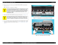
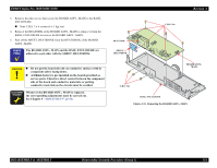
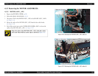
EPSON Stylus Pro 3800/3800C/3850 4.3.4.3 AC INLET 1. Remove the BASE, ENCLOSURE. (p110) 2. Disconnect the HARNESS, AC INLET from CN1 on the BOARD ASSY., POWER SUPPLY. 3. Cut the cable tie that secures the HARNESS, AC INLET to the BASE, ENCLOSURE. 4. Remove the screw that secures the grounding wire to the BASE, ENCLOSURE. „ One C.B.(O). 4 x 8 screw (6 ± 1 kgf.cm) 5. Remove the two screws that secure the AC INLET to the BASE, ENCLOSURE. „ Two C.F.S. 3 x 6 screws (6 ± 1 kgf.cm) 6. Remove the AC INLET from the notch of the BASE, ENCLOSURE. Revision A CN1 HARNESS, AC INLET Grounding Wire C.F.S. 3x6 cable tie C.B.(O). 4x8 BASE, ENCLOSURE AC INLET Figure 4-35. Removing the AC INLET DISASSEMBLY & ASSEMBLY Disassembly/Assembly Procedure (Group 1) 116
-
 1
1 -
2
-
3
-
4
-
5
-
6
-
7
-
8
-
9
-
10
-
11
-
12
-
13
-
14
-
15
-
16
-
17
-
18
-
19
-
20
-
21
-
22
-
23
-
24
-
25
-
26
-
27
-
28
-
29
-
30
-
31
-
32
-
33
-
34
-
35
-
36
-
37
-
38
-
39
-
40
-
41
-
42
-
43
-
44
-
45
-
46
-
47
-
48
-
49
-
50
-
51
-
52
-
53
-
54
-
55
-
56
-
57
-
58
-
59
-
60
-
61
-
62
-
63
-
64
-
65
-
66
-
67
-
68
-
69
-
70
-
71
-
72
-
73
-
74
-
75
-
76
-
77
-
78
-
79
-
80
-
81
-
82
-
83
-
84
-
85
-
86
-
87
-
88
-
89
-
90
-
91
-
92
-
93
-
94
-
95
-
96
-
97
-
98
-
99
-
100
-
101
-
102
-
103
-
104
-
105
-
106
-
107
-
108
-
109
-
110
-
 111
111 -
 112
112 -
 113
113 -
 114
114 -
 115
115 -
 116
116 -
 117
117 -
 118
118 -
 119
119 -
 120
120 -
 121
121 -
122
-
123
-
124
-
125
-
126
-
127
-
128
-
129
-
130
-
131
-
132
-
133
-
134
-
135
-
136
-
137
-
138
-
139
-
140
-
141
-
142
-
143
-
144
-
145
-
146
-
147
-
148
-
149
-
150
-
151
-
152
-
153
-
154
-
155
-
156
-
157
-
158
-
159
-
160
-
161
-
162
-
163
-
164
-
165
-
166
-
167
-
168
-
169
-
170
-
171
-
172
-
173
-
174
-
175
-
176
-
177
-
178
-
179
-
180
-
181
-
182
-
183
-
184
-
185
-
186
-
187
-
188
-
189
-
190
-
191
-
192
-
193
-
194
-
195
-
196
-
197
-
198
-
199
-
200
-
201
-
202
-
203
-
204
-
205
-
206
-
207
-
208
-
209
-
210
-
211
-
212
-
213
-
214
-
215
-
216
-
217
-
218
-
219
-
220
-
221
-
222
-
223
-
224
-
225
-
226
-
227
-
228
-
229
-
230
-
231
-
232
-
233
-
234
-
235
-
236
-
237
-
238
-
239
-
240
-
241
-
242
-
243
-
244
-
245
-
246
-
247
-
248
-
249
-
250
-
251
-
252
-
253
-
254
-
255
-
256
-
257
-
258
-
259
-
260
-
261
-
262
-
263
-
264
-
265
-
266
-
267
-
268
-
269
-
270
-
271
-
272
-
273
-
274
-
275
-
276
-
277
-
278
-
279
-
280
-
281
-
282
-
283
-
284
-
285
-
286
 |
 |
