Epson ActionScanner II Mac Product Information Guide - Page 3
Scanners, ActionScanner II-3, min 250 ns, output, min 0.5 us, STROBE O, BUSY I, ACKNLG I, DATA
 |
View all Epson ActionScanner II Mac manuals
Add to My Manuals
Save this manual to your list of manuals |
Page 3 highlights
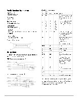
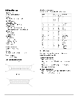
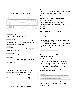
EPSON ACTIONSCANNER II Parallel Interface Specifications Interface type: Bidirectional parallel Data format: 8-bit parallel Synchronization: By external strobe pulse Handshaking: By ACKNLG and BUSY signals Logic level: Input/output data and interface control signals are TTL-level compatible Connector type: 36-pin Centronics® type connector Connector pin arrangement: 18 1 36 19 Timing Charts The figures below show the timing for the bidirectional parallel interface as viewed from the scanner. OUT (from scanner to computer) STROBE (O) BUSY (I) ACKNLG (I) DATA (I) DIR (O) min 250 ns min 0.5 uI s (output) IN (from computer to scanner) min 0.5 Ius STROBE (O) BUSY (I) ACKNLG (I) typ 5 uI s DATA (I) min 0.5 uI s DIR (O) min 0.5 Ius min 0.5 Ius min 0.5 uI s (output) Signal pin assignments Pin No. 1 Return Pin Signal 19 STROBE Direction IN 2 20 3 21 4 22 5 23 6 24 7 25 8 26 9 27 10 28 DATA0 DATA1 DATA2 DATA3 DATA4 DATA5 DATA6 DATA7 ACKNLG IN/OUT IN/OUT IN/OUT IN/OUT IN/OUT IN/OUT IN/OUT IN/OUT OUT 11 29 BUSY OUT 12−15 — NC — Function STROBE pulse to read in or send out data. Pulse width must be more than 0.5 microseconds at the receiving terminal. These signals represent information of bits 1 to 8 respectively. Each signal is at a high level when data is logical 1 and low when it is logical 0. About a 12-microsecond pulse. Low indicates that data has been received and that the scanner is ready to accept more data. When this signal is high, the scanner cannot receive or send data. The signal is high: 1) during data entry 2) when the scanner is not ready 3) when the scanner has an error Not used 16 — 17 — 18 — 19−30 — 31 — GND — C-GND — NC — GND — INIT IN 32 — NC — 33 — GND — 34−35 — NC — Logical ground level Scanner chassis ground Not used Twisted-pair return signal ground level When this signal level becomes low, the scanner is reset to the state when power is turned on. This level is usually High. The pulse width must be more than 50 microseconds at the receiving terminal. Not used Twisted-pair return signal ground level Not used 36 — DIR IN Low indicates the direction is input “Return Pin” denotes the twisted-pair return, to be connected at signal ground level. For interface wiring, be sure to use a twisted-pair cable for each signal, and to complete the connection on the return side. These cables should be shielded and the ground connected to the chassis of the host computer and the scanner. All interface conditions are based on TTL level. Scanners 10/95 ActionScanner II-3
-
 1
1 -
 2
2 -
 3
3 -
 4
4 -
 5
5 -
 6
6
 |
 |
