Epson BrightLink 697Ui Procedure for Measuring Projection Surface Flatness - Page 2
Assessing the Board, Multi-Point Flatness Test
 |
View all Epson BrightLink 697Ui manuals
Add to My Manuals
Save this manual to your list of manuals |
Page 2 highlights
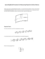
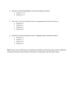
Assessing the Board - Multi-Point Flatness Test The projection surface may be concave or convex or have other irregularities that will affect the calibration and performance of the touch functionality. For this reason it is important to conduct a multi-point flatness measurement. Perform the following Multi-Point Flatness Test to determine if the projection surface is flat enough to proceed with installation of the BrightLink projector: 1. Divide the projection surface equally into 16 quadrants as shown below. 1. With the level tool(s) against the surface of the board at locations described in Steps 2 - 6, insert the 5mm thickness gauge at each position point on the projection surface. If the 5mm gauge is prevented from fitting under the level tool, the surface flatness is less than 5mm and it may be used for installing the BrightLink touch module. 2. Place the 4' level tool VERTICALLY across the projection surface at: a. Position 1, 4, 7 b. Position 2, 5, 8 c. Position 3, 6, 9 3. Place the 5' level tool HORIZONTALLY across the projection surface at: a. Position 1, 2, 3 b. Position 4, 5, 6 c. Position 7, 8, 9
-
 1
1 -
 2
2 -
 3
3
 |
 |
