Epson BrightLink 697Ui Procedure for Measuring Projection Surface Flatness - Page 3
level tool at position 8 and in a sweeping motion check the surface
 |
View all Epson BrightLink 697Ui manuals
Add to My Manuals
Save this manual to your list of manuals |
Page 3 highlights
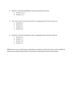
4. Place the 5' level tool DIAGONALLY across the projection surface at: a. Position 1, 5, 9 b. Position 3, 5, 7 5. Place the 5' level tool at position 8 and in a sweeping motion check the surface at: a. Position 8, 4 b. Position 8, 1 c. Position 8, 3 d. Position 8, 6 6. Place the 5' level tool at position 2 and in a sweeping motion check the surface at: a. Position 2, 4 b. Position 2, 7 c. Position 2, 9 d. Position 2, 6 Note: If there are any visible bumps or indentations elsewhere on the board surface, perform additional horizontal and vertical measurements at those points as described in the instructions above.
-
 1
1 -
 2
2 -
 3
3
 |
 |

4.
Place the 5
’
level tool DIAGONALLY across the projection surface at:
a.
Position 1, 5, 9
b.
Position 3, 5, 7
5.
Place the 5
’
level tool at position 8 and in a sweeping motion check the surface at:
a.
Position 8, 4
b.
Position 8, 1
c.
Position 8, 3
d.
Position 8, 6
6.
Place the 5
’
level tool at position 2 and in a sweeping motion check the surface at:
a.
Position 2, 4
b.
Position 2, 7
c.
Position 2, 9
d.
Position 2, 6
Note:
If there are any visible bumps or indentations elsewhere on the board surface, perform additional
horizontal and vertical measurements at those points as described in the instructions above.