Epson BrightLink 710Ui Installation Guide - Control Pad and Touch Unit - Page 22
the same color blue and green on either side.
 |
View all Epson BrightLink 710Ui manuals
Add to My Manuals
Save this manual to your list of manuals |
Page 22 highlights
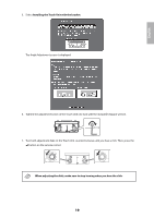
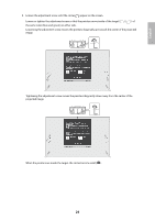
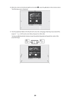
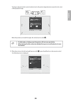
English 9. Loosen the adjustment screw until the circles appear on the screen. Loosen or tighten the adjustment screw so that the pointers move inside of the target ( ) ( ) of the same color (blue and green) on either side. Loosening the adjustment screw moves the pointers diagonally up towards the center of the projected image. Tightening the adjustment screw moves the pointers diagonally down away from the center of the projected image. When the pointers are inside the target, the circles become solid ( ). 21
-
 1
1 -
2
-
3
-
4
-
5
-
6
-
7
-
8
-
9
-
10
-
11
-
12
-
13
-
14
-
15
-
16
-
 17
17 -
 18
18 -
 19
19 -
 20
20 -
 21
21 -
 22
22 -
 23
23 -
 24
24 -
 25
25 -
 26
26 -
 27
27 -
28
-
29
-
30
-
31
-
32
-
33
-
34
-
35
-
36
-
37
-
38
-
39
-
40
-
41
-
42
-
43
-
44
-
45
-
46
-
47
-
48
-
49
-
50
-
51
-
52
-
53
-
54
-
55
-
56
-
57
-
58
-
59
-
60
-
61
-
62
-
63
-
64
-
65
-
66
-
67
-
68
-
69
-
70
-
71
-
72
-
73
-
74
-
75
-
76
-
77
-
78
-
79
-
80
-
81
-
82
-
83
-
84
-
85
-
86
-
87
-
88
-
89
-
90
 |
 |

21
English
9.
Loosen the adjustment screw until the circles
appear on the screen.
Loosen or tighten the adjustment screw so that the pointers move inside of the target (
) (
)
of
the same color (blue and green) on either side.
Loosening the adjustment screw moves the pointers diagonally up towards the center of the projected
image.
Tightening the adjustment screw moves the pointers diagonally down away from the center of the
projected image.
When the pointers are inside the target, the circles become solid (
).