Fisher and Paykel DD24SI7 BOOK INSTL DD24S PH7 US CA EN (English)
Fisher and Paykel DD24SI7 Manual
 |
View all Fisher and Paykel DD24SI7 manuals
Add to My Manuals
Save this manual to your list of manuals |
Fisher and Paykel DD24SI7 manual content summary:
- Fisher and Paykel DD24SI7 | BOOK INSTL DD24S PH7 US CA EN (English) - Page 1
INSTALLATION INSTRUCTIONS DishDrawerTM dishwasher DD24S 7 & DD24ST 7 models US CA 590204C 03.12 - Fisher and Paykel DD24SI7 | BOOK INSTL DD24S PH7 US CA EN (English) - Page 2
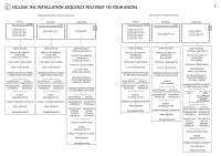
2 Classic STANDARD HEIGHT SINGLE MODELS Designer Integrated Classic TALL HEIGHT SINGLE MODELS Designer Integrated DD24SCX7 DD24SCW7 DD24SCB7 DD24SDFX7 DD24SI7 DD24SCTX7 DD24SCHTX7 DD24SCTW7 DD24SCTB7 DD24SDFTX7 DD24STI7 DD24SHTI7 PARTS SUPPLIED PRODUCT & CABINETRY DIMENSIONS (STANDARD - Fisher and Paykel DD24SI7 | BOOK INSTL DD24S PH7 US CA EN (English) - Page 3
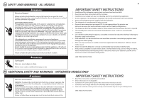
service technician's travel to the location of the product. SAVE THESE INSTRUCTIONS 2b ADDITIONAL SAFETY AND WARNINGS - INTEGRATED MODELS ONLY WARNING! Electrical Shock Hazard WARNING: To reduce the risk of electrical shock, fire, or injury to persons, the installer must ensure that the dishwasher - Fisher and Paykel DD24SI7 | BOOK INSTL DD24S PH7 US CA EN (English) - Page 4
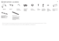
3a PARTS SUPPLIED - ALL MODELS 4 Drain hose support (1) Drain hose joiner (1) Wire clip (1) (for securing services, you must use a Drain Hose Extension Kit P/N 525798 which will extend the drain hoses by 11' 10" (3.6m). The kit is available from the nearest Fisher & Paykel Authorized Service - Fisher and Paykel DD24SI7 | BOOK INSTL DD24S PH7 US CA EN (English) - Page 5
3b ADDITIONAL PARTS SUPPLIED WITH INTEGRATED MODELS 5 External Venting kit (1) Panel bracket (1) (attached to product) Panel mounting screws (6) - Fisher and Paykel DD24SI7 | BOOK INSTL DD24S PH7 US CA EN (English) - Page 6
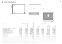
4 PRODUCT DIMENSIONS K H AI Side J G Plan DC F B 6 E Product dimensions inches (mm) STANDARD HEIGHT MODELS TALL HEIGHT MODELS Integrated 18 7⁄8" (480 mm) cavity Integrated 18" (456 mm) cavity Designer Classic Integrated Designer Classic A overall height1 of product (incl. front panel - Fisher and Paykel DD24SI7 | BOOK INSTL DD24S PH7 US CA EN (English) - Page 7
with your cabinetry or companion products Standard height models Tall height Classic models Tall height Designer models L min. 16 ¼" (412 mm) Dishwasher L 18 " (456 mm) Dishwasher Oven L 18 7⁄8" (480 mm) Dishwasher CoolDrawer Minimum clearances from adjacent cabinetry min. ½" (13 - Fisher and Paykel DD24SI7 | BOOK INSTL DD24S PH7 US CA EN (English) - Page 8
6 INTEGRATED MODELS ONLY - CUSTOM FRONT PANEL CALCULATIONS 8 FRONT PANEL SPECIFICATIONS 5⁄8 - 13⁄16" (16 HEIGHT OF PANEL B (min. 1⁄16" (2 mm)) - = Note: when the top of the dishwasher has to be lower than the adjacent cabinetry, the panel can be increased in height. min. 1⁄16" (2mm) - Fisher and Paykel DD24SI7 | BOOK INSTL DD24S PH7 US CA EN (English) - Page 9
7 OPTIONALLY HARD WIRING PRIOR TO INSTALLATION 9 7a REMOVE THE DRAWER 43 1 Product may move. Mark chassis position on cavity Access cover 2 To prevent kinked hoses, we recommend rotating the drawer counter-clockwise and re5sting it on its side after removal. 3 4"1(01000mmmm) Press the release - Fisher and Paykel DD24SI7 | BOOK INSTL DD24S PH7 US CA EN (English) - Page 10
Services can be located either side of the dishwasher. ø max. 1½"(38 mm) max. 17 11⁄16" (450 mm) Services hole Can be located either side of dishwasher compression fitting. Water Pressure Water softener models Max. 1 MPa (145 psi) Min. 0.1 MPa (14.5 psi) Models without water softener Max. 1 MPa - Fisher and Paykel DD24SI7 | BOOK INSTL DD24S PH7 US CA EN (English) - Page 11
INLET HOSE + POWER CORD 8 11⁄16" (220 mm) 4" (100 mm) 9b INTEGRATED MODELS ONLY - PREPARATION FOR EXTERNAL VENTING THROUGH ADJACENT CABINET Services can be located either side of dishwasher ø 2 3⁄8" 60mm The ø 2 3⁄8" (60 mm) services hole for the hoses should be enlarged to accomodate the extra - Fisher and Paykel DD24SI7 | BOOK INSTL DD24S PH7 US CA EN (English) - Page 12
EDGE 12 Left hand side Drain hose - 78 ½" (2000 mm) Inlet hose - 64 ¾" (1650 mm) Power cord (excl. plug) - 29 ½" (750 mm) Venting hose - 60 1⁄16" (1525 mm) (Integrated models only) Right hand side Drain hose - 70 ½" (1800 mm) Inlet hose - 49" (1250 mm) Power cord (excl. plug) - 27 ½" (700 mm - Fisher and Paykel DD24SI7 | BOOK INSTL DD24S PH7 US CA EN (English) - Page 13
11 DESIGNER & INTEGRATED TALL MODELS FOR 18 7⁄8" (480 mm) CAVITY ONLY - ATTACH CAVITY BRACKET 13 The enclosed cavity bracket is fitted before installation in order to conceal the gap at - Fisher and Paykel DD24SI7 | BOOK INSTL DD24S PH7 US CA EN (English) - Page 14
slots are in pairs, B one on each side diagonally across the product. A bracket must match A slot and B bracket must match B slot. 13a INTEGRATED ONLY - ATTACH VENTING HOSE Check that the fitted elbow is rotated left or right (depending on the direction of the routing), then ensure the - Fisher and Paykel DD24SI7 | BOOK INSTL DD24S PH7 US CA EN (English) - Page 15
HOSES & MOVE INTO THE CAVITY Vent Hose (Integrated models only) vent either through same cabinet or adjacent squash the hoses and lead to incorrect operation. 16a INTEGRATED ONLY - SECURE THE EXTERNAL VENT 15a SECURE THE DRAWER Open the drawer halfway. Using a flat-bladed screwdriver, prize - Fisher and Paykel DD24SI7 | BOOK INSTL DD24S PH7 US CA EN (English) - Page 16
is rotated left or right (depending on the direction of the routing), then ensure the venting hose is securely attached to it. Fitted Elbow 13b PULL THROUGH HOSES & MOVE INTO THE CAVITY Vent Hose (Integrated models only) vent either through same cabinet or adjacent cabinet as per step 9a or 9b As - Fisher and Paykel DD24SI7 | BOOK INSTL DD24S PH7 US CA EN (English) - Page 17
use 5⁄8" (16 mm) screws) 1 2 a pair of fixing holes on the bottom (use 1 ½" (38 mm) fixing screws & washers) 17b INTEGRATED ONLY - SECURE THE EXTERNAL VENT 159 148 Ensure the release tabs on 115 both sides are reset fully. Before refitting the drawer, ensure the hoses are not twisted and the - Fisher and Paykel DD24SI7 | BOOK INSTL DD24S PH7 US CA EN (English) - Page 18
INTEGRATED MODELS ONLY - INSTALLING THE FRONT PANEL 18 18 REMOVE BRACKET FROM PRODUCT WARNING! Electrical Shock Hazard Before continuing, ensure that the product is disconnected from the - Fisher and Paykel DD24SI7 | BOOK INSTL DD24S PH7 US CA EN (English) - Page 19
INTEGRATED MODELS ONLY - INSTALLING THE FRONT PANEL 19 22 ADJUST PANEL HEIGHT TO ALIGN THE CABINETRY GAPS + or - 1⁄16" (2 mm) With the front panels fitted, insert an - Fisher and Paykel DD24SI7 | BOOK INSTL DD24S PH7 US CA EN (English) - Page 20
OPTIONS. CHOOSE WHICH IS MORE SUITABLE. 20 Dishwasher and Standpipe Ø 1½" (38 mm) Dishwasher using Air Break with Drain Hose Joiner Dishwasher using sink trap with drain hose joiner If space is limited for fixing, push hose through drain 2 hose support to required height mmaax.. 1240¾" (120mmmm - Fisher and Paykel DD24SI7 | BOOK INSTL DD24S PH7 US CA EN (English) - Page 21
, hoses or drawer latches. If a problem occurs, consult the 'Troubleshooting' section of the User guide. If after checking these points you still need assistance, please refer to the Service & Warranty book for warranty details and your nearest Authorized Service Center, or contact us through our
-
 1
1 -
 2
2 -
 3
3 -
 4
4 -
 5
5 -
 6
6 -
 7
7 -
8
-
9
-
10
-
11
-
12
-
13
-
14
-
15
-
16
-
17
-
18
-
19
-
20
-
21
 |
 |

590204C
03.12
US CA
INSTALLATION INSTRUCTIONS
DishDrawer
TM
dishwasher
DD24S 7 & DD24ST 7 models