Fluke 117 Fluke 114,115,117 Manual - Page 6
Display - user manual
 |
View all Fluke 117 manuals
Add to My Manuals
Save this manual to your list of manuals |
Page 6 highlights
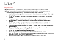
114, 115, and 117 Users Manual Display No. A B C D E 4 Symbol w s R O Y 6 5 4 3 2 1 16 15 VoltAlert 7 14 17 8 9 10 11 12 13 18 Meaning The Meter is in the VoltAlert™ non-contact voltage detect mode. The Meter function is set to Continuity. The Meter function is set to Diode Test Input is a negative value. X Unsafe voltage. Measured input voltage ≥30 V, or voltage overload condition (OL). edy02f.eps Model 117 114, 115, & 117 115 & 117 114, 115, & 117 114, 115, & 117
-
 1
1 -
 2
2 -
 3
3 -
 4
4 -
 5
5 -
 6
6 -
 7
7 -
 8
8 -
 9
9 -
 10
10 -
 11
11 -
 12
12 -
13
-
14
-
15
-
16
-
17
-
18
-
19
-
20
-
21
-
22
-
23
-
24
-
25
-
26
 |
 |

114, 115, and 117
Users Manual
4
Display
VoltAlert
11
7
17
18
12
13
14
9
6
5
4
3
2
1
16
15
8
10
edy02f.eps
No.
Symbol
Meaning
Model
A
w
The Meter is in the VoltAlert™ non-contact voltage detect mode.
117
B
s
The Meter function is set to Continuity.
114, 115, & 117
C
R
The Meter function is set to Diode Test
115 & 117
D
O
Input is a negative value.
114, 115, & 117
E
Y
X
Unsafe voltage. Measured input voltage
≥
30 V, or voltage
overload condition (OL).
114, 115, & 117