Fluke 789 Calibration Manual
Fluke 789 Manual
 |
View all Fluke 789 manuals
Add to My Manuals
Save this manual to your list of manuals |
Fluke 789 manual content summary:
- Fluke 789 | Calibration Manual - Page 1
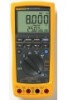
789 ProcessMeter™ Calibration Manual September 2002, Rev.1, 3/13 © 2002-2013 Fluke Corporation. All rights reserved. Specifications are subject to change without notice. All product names are trademarks of their respective companies. - Fluke 789 | Calibration Manual - Page 2
warranty on behalf of Fluke. Warranty support is available only if product is purchased through a Fluke authorized sales outlet or Buyer has paid the applicable international price. Fluke reserves the right to invoice Buyer for importation costs of repair/replacement parts when product purchased in - Fluke 789 | Calibration Manual - Page 3
Symbols ...3 Specifications...4 Required Equipment 7 Basic Maintenance 8 Cleaning the ProcessMeter 8 Replacing the Batteries 8 Battery Life...9 Checking and Replacing the Fuses 10 Calibration Verification 10 Preparing to Perform Calibration Verification 11 Loop Power 11 Current Sourcing 13 - Fluke 789 | Calibration Manual - Page 4
789 Calibration Manual ii - Fluke 789 | Calibration Manual - Page 5
Life 9 4. Current Sourcing Test 13 5. DC mA Test ...15 6. DC Amp Test ...15 7. AC Amp Test ...15 8. Resistance Measurement Test Using a 5500A or 5520A Calibrator 19 9. DC mV Test ...20 10. DC Volts Test...22 11. AC Volts Test...22 12. Frequency Measurement Test 23 13. Replacement Parts 32 iii - Fluke 789 | Calibration Manual - Page 6
789 Calibration Manual iv - Fluke 789 | Calibration Manual - Page 7
Title Page 1. Replacing the Batteries and Fuses 9 2. Verifying Loop Power 12 3. Current Sourcing Connections Using the HP 3458A 13 4. Current Measurement Test Connections 14 5. Diode Test Connections 16 6. Continuity Test Connections 17 7. Resistance Measurement Test Connections 18 8. DC - Fluke 789 | Calibration Manual - Page 8
789 Calibration Manual vi - Fluke 789 | Calibration Manual - Page 9
test procedures • Calibration adjustment procedures • Accessories and replaceable parts For complete operating instructions, refer to the 789 ProcessMeter Users Manual (on the CD-ROM provided). How to Contact Fluke To contact Fluke, call one of the following telephone numbers: • Technical Support - Fluke 789 | Calibration Manual - Page 10
have the meter serviced. • Do not operate the meter around explosive gas, vapor, or dust. • Do not use in a damp or wet environment. • Use only type AA batteries, properly installed in the meter case, to power the meter. • When servicing the meter, use only specified replacement parts. • Use caution - Fluke 789 | Calibration Manual - Page 11
Symbols Symbols used on the ProcessMeter and in this calibration manual are explained in Table 1. Symbol CAT II CAT III CAT IV Table 1. International Symbols Meaning Symbol Meaning Risk of danger. Important information. See Manual. Hazardous voltage Conforms to European - Fluke 789 | Calibration Manual - Page 12
789 Calibration Manual Specifications All specifications apply from +18 °C to +28 °C unless stated otherwise. All specifications assume a 5-minute warm-up period. The standard specification interval is 1 year. Note "Counts" refers to the number of increments or decrements of the least significant - Fluke 789 | Calibration Manual - Page 13
1 A 30 seconds maximum Specifications are valid from 5 % to 100 % of amplitude range. AC conversion: true rms Maximum crest factor: 3 (between 50 and 60 Hz) For non-sinusoidal waveforms, add ±( 2 % reading + 2 % f.s.) typical Overload protection 440 mA, 1000 V fast-blow fuse Typical Burden Voltage - Fluke 789 | Calibration Manual - Page 14
Loop Power Supply: Minimum 24 V@ 24 mA into 1200 Ω load DC Current Output Source mode: Span: 0 mA or 4 mA to 20 mA, with overrange to 24 mA Accuracy: 0.05 % of span[1] (span: 0 to 20 mA) Compliance voltage: 28 V with battery voltage > ~4.5 V [1] 0.1 x specified accuracy per °C for temperatures - Fluke 789 | Calibration Manual - Page 15
Unless otherwise indicated, all connection diagrams for the calibration verification tests in this manual showing a calibrator or digital multimeter use a Fluke 5500A calibrator or Agilent 3458A. If you are using a different calibrator or DMM, make the connections appropriate for that instrument. 7 - Fluke 789 | Calibration Manual - Page 16
789 Calibration Manual Equipment Calibration Source Digital Process Meter or Digital Process Calibrator Digital Multimeter Test Leads, low leakage, RG-58/U type 1-kΩ shunt Table 2. Required Equipment and Software Minimum Specifications Recommended Model No Substitute No Substitute No Substitute - Fluke 789 | Calibration Manual - Page 17
. • Avoid using the backlight. • Do not disable the automatic power-off feature. • Turn the ProcessMeter off when not in use. Table 3. Typical Alkaline Battery Life ProcessMeter Operation Measuring any parameter 140 Simulating Current 140 Sourcing 12 mA into 500 Ω 10 Hours anw037.eps 9 - Fluke 789 | Calibration Manual - Page 18
789 Calibration Manual Checking and Replacing the Fuses Warning To avoid personal injury or damage to the ProcessMeter, use only the specified replacement fuse, 440 mA 1000 V fast-blow, Fluke PN 943121. Both current input jacks are fused with separate 440 mA fuses. To determine if a fuse is blown - Fluke 789 | Calibration Manual - Page 19
2. Unless otherwise indicated, all connection diagrams for the calibration verification tests in this manual showing a calibrator or digital multimeter use a Fluke 5500A calibrator or HP 3458A. If using a different calibrator or DMM make the connections appropriate for your instrument. To prepare - Fluke 789 | Calibration Manual - Page 20
789 Calibration Manual Loop Power 1. Enable the dc volts autorange function of the HP3458A multimeter. 2. Turn the rotary knob of the UUT to LOOP POWER. 3. Measure the open circuit voltage of the UUT and verify it is >29.8 V and - Fluke 789 | Calibration Manual - Page 21
Sourcing Test 789 Range No Range Switching No Range Switching No Range Switching 789 Output Current 4.000 mA 12.000 mA 20.000 mA Minimum Acceptable Multimeter Reading 3.990 mA 11.990 mA 19.990 mA Maximum Acceptable Multimeter Reading 4.010 mA 12.010 mA 20.010 mA HP 3458A DC mA Function 100 mA - Fluke 789 | Calibration Manual - Page 22
789 Calibration Manual Current Measurement 1. Put the calibrator in Standby (STBY) mode. W 2. Put the UUT rotary switch in the position. 3. Connect the calibrator to the COM and mA terminals on the UUT as shown in Figure 4. 4. Apply the values from the calibrator shown in Table 5 and compare the - Fluke 789 | Calibration Manual - Page 23
dc mA (autorange) function. 9. Connect the current terminals of the multimeter to the COM and terminals on the UUT. 10. The multimeter should read close to 0.2 mA. (There is no tolerance specification for this current. This test just makes sure that the diode test current source is operating.) 15 - Fluke 789 | Calibration Manual - Page 24
789 Calibration Manual UUT (BLUE) 5500A HP 3458A DC mA Autorange Function Figure 5. Diode Test Connections adm007F.EPS 16 - Fluke 789 | Calibration Manual - Page 25
as shown in Figure 6. 3. Press G (continuity beeper) on the UUT to select the continuity test. 4. Using the calibrator, apply a resistance output of 230 ± 20 Ω. The beeper should stay off. 5. Using the calibrator, apply a resistance output of 120 ± 20 Ω. The beeper should turn on. UUT 5500A Figure - Fluke 789 | Calibration Manual - Page 26
789 Calibration Manual Resistance Measurement Test 1. Put the calibrator in Standby (STBY) mode. 2. Put the UUT rotary switch in the V position. 3. Connect the OUTPUT and SENSE leads of the calibrator to the UUT as shown by the solid and dotted lines in Figure 7. 4. Apply the calibrator resistance - Fluke 789 | Calibration Manual - Page 27
ProcessMeter™ Calibration Verification Table 8. Resistance Measurement Test Using a 5500A or 5520A Calibrator 789 Range Calibrator Resistance Calibrator Compensation Mode Minimum Reading Maximum Reading 400 Ω 400 Ω 4 kΩ 4 kΩ 40 kΩ 40 kΩ 400 kΩ 400 kΩ 400 kΩ 4 MΩ 4 MΩ 40 MΩ 40 MΩ 120 Ω 300 Ω - Fluke 789 | Calibration Manual - Page 28
789 Calibration Manual DC Millivolts Measurement Test 1. Put the calibrator in Standby (STBY) mode. 2. Put the UUT rotary switch in the U position. 3. Connect the calibrator to the COM and terminals on the UUT as shown in Figure 8. 4. Apply the values from the calibrator shown in Table 9 and - Fluke 789 | Calibration Manual - Page 29
ProcessMeter™ Calibration Verification DC Volts Measurement Tests Warning To prevent possible electrical shock, fire, or personal injury: • Some of the calibration verification tests involve the use of high voltages and should be performed by qualified personnel only. • Always place the - Fluke 789 | Calibration Manual - Page 30
789 Calibration Manual 789 Range 4 V dc 4 V dc 40 V dc 40 V dc 400 V dc 400 V dc 1000 V dc 1000 V dc Table 10. DC Volts Test Calibrator DC Voltage Minimum Reading 1 V 3 V 10 V 30 V 100 V 300 V 100 V 800 V 0.998 V 2.996 V 9.98 V 29.96 V 99.8 V 299.6 V 99 798 Maximum Reading 1.002 V 3.004 V 10. - Fluke 789 | Calibration Manual - Page 31
shown in Table 12 and compare the readings on the UUT to the acceptable readings shown. 789 Range 199.99 Hz 1999.9 Hz 19.999 kHz Table 12. Frequency Measurement Test Calibrator Voltage and Frequency Minimum Acceptable Reading 5 V @ 100 Hz 5 V @ 1000 Hz 5 V @ 10 kHz 99.98 Hz 999.8 Hz 9.998 - Fluke 789 | Calibration Manual - Page 32
before using it. • Check the test leads for continuity. Replace damaged test leads as necessary. • Do not use the ProcessMeter if it appears to operate abnormally. Protection designed into the ProcessMeter might be impaired. If in doubt, have the ProcessMeter serviced. • To avoid electrical shock - Fluke 789 | Calibration Manual - Page 33
UUT are intact. See "Checking and Replacing the Fuses" earlier in this manual. 3. Turn on and warm up the calibrator as required by its specifications. 4. Remove all input cables from the front of the UUT. 5. Make sure that the UUT is in an ambient temperature between 18 °C and 28 °C (64.4 °F and - Fluke 789 | Calibration Manual - Page 34
789 Calibration Manual Calibration Button Figure 11. Calibration Button Access aau04f.eps Frequency Adjustment 1. Connect the ProcessMeter to the volt/ohm output of the 5500A calibrator. 2. Turn the UUT's switch to S. 3. Push h. 4. Press and hold the Calibration Button for approximately 2 - Fluke 789 | Calibration Manual - Page 35
button is pressed a second time. CAL appears in the bottom display when the ProcessMeter is in calibration mode. 4. Press after each sourced value appears. Do not alter the sourced value while the display reads Busy. Applied voltages: • 0V • 4V • 40 V • 400 V • 1000 V 5. When Store is displayed - Fluke 789 | Calibration Manual - Page 36
789 Calibration Manual DC Millivolts Adjustment 1. Connect the ProcessMeter to the volt/ohm output of the 5500A calibrator. 2. Turn the UUT's switch to U. 3. Press and hold the Calibration Button for approximately 2 seconds. The unit will beep (see Figure 11). Note Pressing the Calibration Button - Fluke 789 | Calibration Manual - Page 37
not alter the sourced value while the display reads Busy. 7. When Store is displayed, press to store the calibration value. Milliamps DC Adjustment 1. Connect the ProcessMeter to the mA output of the 5500A calibrator. W 2. Turn the UUT's switch to . Make sure the test leads are in the mA and COM - Fluke 789 | Calibration Manual - Page 38
789 Calibration Manual Amps DC Adjustment 1. Connect the ProcessMeter to the A output of the 5500A calibrator. 2. Turn the UUT's switch to W. Make sure the test leads are in the A and COM jacks. 3. Press and hold the Calibration Button for 2 seconds (see Figure 11). The unit will beep. 4. Apply 0 A - Fluke 789 | Calibration Manual - Page 39
the specified replacement fuse, 440 mA 1000 V fast-blow, Fluke PN 943121. Note When servicing the ProcessMeter, use only the replacement parts specified here. Replacement parts and some accessories are shown in Figure 12 and listed in Table 13. Many more DMM accessories are available from Fluke. For - Fluke 789 | Calibration Manual - Page 40
789 Calibration Manual Table 13. Replacement Parts Item Number Reference Designator Description Fluke PN or Model no. Quantity MP14 Knob Assembly 658440 MP1 Top Case with Lens Protector 1622862 MP8 Decal, Top Case 1623923 D MP6 Keypad 1622951 E MP5 Top Shield 1622924
-
 1
1 -
 2
2 -
 3
3 -
 4
4 -
 5
5 -
 6
6 -
 7
7 -
8
-
9
-
10
-
11
-
12
-
13
-
14
-
15
-
16
-
17
-
18
-
19
-
20
-
21
-
22
-
23
-
24
-
25
-
26
-
27
-
28
-
29
-
30
-
31
-
32
-
33
-
34
-
35
-
36
-
37
-
38
-
39
-
40
 |
 |

789
ProcessMeter™
Calibration Manual
September 2002, Rev.1, 3/13
© 2002-2013 Fluke Corporation. All rights reserved. Specifications are subject to change without notice.
All product names are trademarks of their respective companies.