Fluke 83V FE 83V & 87V Users Manual - Page 26
Measuring Resistance, power and discharge all high-voltage
 |
View all Fluke 83V manuals
Add to My Manuals
Save this manual to your list of manuals |
Page 26 highlights
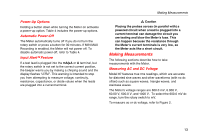
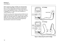
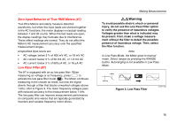
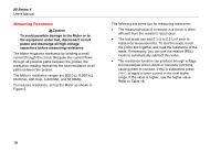
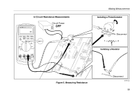
80 Series V Users Manual Measuring Resistance WCaution To avoid possible damage to the Meter or to the equipment under test, disconnect circuit power and discharge all high-voltage capacitors before measuring resistance. The Meter measures resistance by sending a small current through the circuit. Because this current flows through all possible paths between the probes, the resistance reading represents the total resistance of all paths between the probes. The Meter's resistance ranges are 600.0 Ω, 6.000 kΩ, 60.00 kΩ, 600.0 kΩ, 6.000 MΩ, and 50.00MΩ. To measure resistance, set up the Meter as shown in Figure 5. The following are some tips for measuring resistance: • The measured value of a resistor in a circuit is often different from the resistor's rated value. • The test leads can add 0.1 Ω to 0.2 Ω of error to resistance measurements. To test the leads, touch the probe tips together and read the resistance of the leads. If necessary, you can use the relative (REL) mode to automatically subtract this value. • The resistance function can produce enough voltage to forward-bias silicon diode or transistor junctions, causing them to conduct. If this is suspected, press C to apply a lower current in the next higher range. If the value is higher, use the higher value. Refer to Table 18. 18
-
 1
1 -
2
-
3
-
4
-
5
-
6
-
7
-
8
-
9
-
10
-
11
-
12
-
13
-
14
-
15
-
16
-
17
-
18
-
19
-
20
-
 21
21 -
 22
22 -
 23
23 -
 24
24 -
 25
25 -
 26
26 -
 27
27 -
 28
28 -
 29
29 -
 30
30 -
 31
31 -
32
-
33
-
34
-
35
-
36
-
37
-
38
-
39
-
40
-
41
-
42
-
43
-
44
-
45
-
46
-
47
-
48
-
49
-
50
-
51
-
52
-
53
-
54
-
55
-
56
-
57
-
58
-
59
-
60
 |
 |