Fluke 9143-A-P-156 Product Manual
Fluke 9143-A-P-156 Manual
 |
View all Fluke 9143-A-P-156 manuals
Add to My Manuals
Save this manual to your list of manuals |
Fluke 9143-A-P-156 manual content summary:
- Fluke 9143-A-P-156 | Product Manual - Page 1
914X Series Field Metrology Well User's Guide Revision 7A1901-EN MyFlukeStore Shop for Fluke products online at: www. .com 1.888.610.7664 - Fluke 9143-A-P-156 | Product Manual - Page 2
period begins on the date of the shipment. Parts, product repairs, and services are warranted for 90 days. The warranty extends only to the original buyer extend a greater or different warranty on behalf of Hart. Warranty support is available if product is purchased through a Hart authorized sales - Fluke 9143-A-P-156 | Product Manual - Page 3
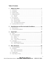
1.5 CE Comments 8 1.5.1 EMC Directive 8 1.5.2 Immunity Testing 8 1.5.3 Emission Testing 9 1.5.4 Low Voltage Directive (Safety 9 1.6 Authorized Service Centers 9 2 Specifications and Environmental Conditions 13 2.1 Specifications 13 2.2 Environmental Conditions 15 3 Quick Start 17 3.1 Setup - Fluke 9143-A-P-156 | Product Manual - Page 4
5 Maintenance 35 5.1 Field Metrology Well Performance Analysis 35 iv MyFlukeStore Shop for Fluke products online at: www. .com 1.888.610.7664 - Fluke 9143-A-P-156 | Product Manual - Page 5
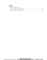
Tables Table 1 Symbols used 3 Table 2 Base Unit Specifications 13 Table 3 -P Option Specifications 14 v MyFlukeStore Shop for Fluke products online at: www. .com 1.888.610.7664 - Fluke 9143-A-P-156 | Product Manual - Page 6
Figure 10 Steps to language selection 27 Figure 11 Main Menu - Temp SetUp 29 Figure 12 Main Menu - Prog Menu 30 Figure 13 Auto and manual switch test operation example 32 Figure 14 Main Menu - System Menu 33 Figure 15 Main Menu - Input Setup 34 vi MyFlukeStore Shop for Fluke products - Fluke 9143-A-P-156 | Product Manual - Page 7
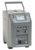
1 Before You Start Before You Start Introduction 1.1 Introduction Field Metrology Wells (9142, 9143, and 9144) are designed to be reliable, stable heat sources that can be used in the field or laboratory. They offer accuracy, portability, and speed for nearly every field calibration application. - Fluke 9143-A-P-156 | Product Manual - Page 8
components are present: 9142 ●● 9142 Field Metrology Well ●● 9142-INSX Insert (X=A, B, C, D, E, or F) ●● Power Cord ●● RS-232 Cable ●● User Guide ●● Technical Manual CD ●● Report of Calibration and calibration label ●● 6-pin DIN Connector (-P model only) ●● Test Lead Kit (-P model only) ●● Well - Fluke 9143-A-P-156 | Product Manual - Page 9
C, D, E, or F) ●● Power Cord ●● RS-232 Cable ●● User Guide ●● Technical Manual CD ●● Report of Calibration and calibration label ●● 6-pin DIN Connector (-P model and User's Guide If all items are not present, contact an Authorized Service Center (see Section 1.6 Authorized Service Centers on page - Fluke 9143-A-P-156 | Product Manual - Page 10
PE Ground Hot Surface (Burn Hazard) Read the User's Guide (Important Information) Off On Canadian Standards Association C-TICK CAN/CSA 22.2 No 61010.1-04. Use this instrument only as specified in this manual. Otherwise, the protection provided by the instrument may be impaired. Refer to the - Fluke 9143-A-P-156 | Product Manual - Page 11
use this instrument in environments other than those listed in the User's Guide. Inspect the instrument for damage before each use. Inspect the case. abnormally. Protection may be impaired. When in doubt, have the instrument serviced. Do not apply more than the rated voltage, as marked on the - Fluke 9143-A-P-156 | Product Manual - Page 12
914X Field Metrology Wells Safety Information Never touch the probes to a voltage source when the test leads are plugged into the current terminals. Select the proper function and range for each measurement. Disconnect the test leads before changing to another measure or source function. DO NOT - Fluke 9143-A-P-156 | Product Manual - Page 13
Before You Start Safety Information If supplied with user accessible fuses, always replace the fuse with one of the same rating, voltage, and type. Always replace the power cord with an approved cord of the correct rating and type. HIGH VOLTAGE is used in the operation of this equipment. SEVERE - Fluke 9143-A-P-156 | Product Manual - Page 14
inserts clean and clear of foreign material. The Field Metrology Well is a precision instrument. Although it has been designed for optimum durability and trouble free operation, it must be handled with care. Always carry the instrument in an upright position to prevent the inserts from dropping out - Fluke 9143-A-P-156 | Product Manual - Page 15
equipment has been designed to meet the EN 61010-1 and the EN 61010-2-010 standards. 1.6 Authorized Service Centers Please contact one of the following Authorized Service Centers to coordinate service on your Hart product: 9 MyFlukeStore Shop for Fluke products online at: www. .com 1.888.610 - Fluke 9143-A-P-156 | Product Manual - Page 16
914X Field Metrology Wells Authorized Service Centers When contacting a Service Centers for support, please have the following information available: ●● Model Number ●● Serial Number ●● Voltage ●● Complete description of the problem 10 MyFlukeStore Shop for Fluke products online at: www. .com 1. - Fluke 9143-A-P-156 | Product Manual - Page 17
11 MyFlukeStore Shop for Fluke products online at: www. .com 1.888.610.7664 - Fluke 9143-A-P-156 | Product Manual - Page 18
MyFlukeStore Shop for Fluke products online at: www. .com 1.888.610.7664 - Fluke 9143-A-P-156 | Product Manual - Page 19
Specifications and Environmental Conditions Specifications 2 Specifications and Environmental Conditions 2.1 Specifications Table 2 Base Unit Specifications Base Unit Specifications 9142 9143 9144 Temperature Range at 23 °C Display Accuracy -25 °C to 150 °C (-13 °F to 302 °F) ± 0.2 °C Full - Fluke 9143-A-P-156 | Product Manual - Page 20
914X Field Metrology Wells Specifications Base Unit Specifications 9142 9143 9144 Weight Power Requirements System Fuse Ratings 4-20 mA Fuse (-P model only) Computer Interface Safety 8.16 kg (18 lbs) 100 V to 115 V (± 10 %) 50/60 Hz, 635 W 230 V (± 10 %) 50/60 Hz, 575 W 115 V: 6.3 A T 250 V - Fluke 9143-A-P-156 | Product Manual - Page 21
possible difference between the resistances of the lead wires. 2.2 Environmental Conditions Although the instrument has been designed for optimum durability and trouble-free operation, it must be handled with care. The instrument should not be operated in an excessively dusty or dirty environment - Fluke 9143-A-P-156 | Product Manual - Page 22
MyFlukeStore Shop for Fluke products online at: www. .com 1.888.610.7664 - Fluke 9143-A-P-156 | Product Manual - Page 23
hole diameter possible still allowing the probe to slide in and out easily. Various insert sizes are available. Contact an Authorized Service Center for assistance (see Section 1.6 Authorized Service Centers on page 9). The well must be clear of any foreign objects, dirt and grit before an insert is - Fluke 9143-A-P-156 | Product Manual - Page 24
914X Field Metrology Wells Parts and Controls Figure 2 914X Field Metrology Well 3.2 Parts and Controls This section describes the exterior features of the Field Metrology Well. All interface and power connections are found on the front of the instrument (see Figure 2). 18 MyFlukeStore Shop for - Fluke 9143-A-P-156 | Product Manual - Page 25
3.2.1 Display Panel Figure 3 on next page shows the layout of the display panel. Quick Start Parts and Controls Display (1) The display is a 240 x 160 pixel monochrome graphics LCD device with a bright LED backlight. The display is used to show current control temperature, measurements, status - Fluke 9143-A-P-156 | Product Manual - Page 26
914X Field Metrology Wells Parts and Controls Block Temperature Indicator (10) [Patent Pending] The Block Temperature Indicator lamp allows users to know when the block temperature is safe (50°C to 60°C) to remove inserts or move the Field Metrology Well. The indicator light is lit continuously once - Fluke 9143-A-P-156 | Product Manual - Page 27
Quick Start Parts and Controls Stability Status (4) On the right hand side of the screen, you will find a graph displaying the current status of the stability of the Field Metrology Well. Heating/Cooling Status (5) Just below the stability graph there is a bar graph that will indicate HEATING, - Fluke 9143-A-P-156 | Product Manual - Page 28
914X Field Metrology Wells Parts and Controls 3.2.3 Power Panel The following are found on the lower front panel of the instrument (see Figures 5 and Figure 6 on opposite page). Power Cord Plug (1) The power supply cord attaches to the lower front power panel. Plug the cord into an AC mains - Fluke 9143-A-P-156 | Product Manual - Page 29
Quick Start Parts and Controls Figure 5 9142 power panel Figure 6 9143 and 9144 power panel 23 MyFlukeStore Shop for Fluke products online at: www. .com 1.888.610.7664 - Fluke 9143-A-P-156 | Product Manual - Page 30
(see Section 1.5.2 Immunity Testing on page 8 for information on using clamp-on ferrites). A PRT is the only type of probe that is supported by the reference thermometer input. The PRT (RTD or SPRT) probe connects to the reference thermometer input using a 6-pin DIN connector. Figure 8 shows - Fluke 9143-A-P-156 | Product Manual - Page 31
Probe Connector 15 6 23 4 Shield Quick Start Parts and Controls RTD Sensor Figure 8 Probe connector wiring A two-wire probe can also be used with the reference thermometer. It is connected by attaching one wire to both pins 1 and 2 of the plug and the other wire to both pins 4 and 5. If a shield - Fluke 9143-A-P-156 | Product Manual - Page 32
914X Field Metrology Wells Languages Figure 9 Jumper locations for 3-wire and 2-wire connections Thermocouple (TC) Connector (4) The TC connector allows for the use of subminiature TC connectors (see CE Comments on page 8 for information on using clamp-on ferrites). Fuse (5) Fuse for the 4-20 mA - Fluke 9143-A-P-156 | Product Manual - Page 33
Quick Start Languages Figure 10 Steps to language selection 3.3.2 Reset to English Language If you are in a language and need a short cut exit, press F1 and F4 simultaneously to reset the display to English. To reset to your originally selected language after resetting to English, follow the - Fluke 9143-A-P-156 | Product Manual - Page 34
MyFlukeStore Shop for Fluke products online at: www. .com 1.888.610.7664 - Fluke 9143-A-P-156 | Product Manual - Page 35
4 Menu Structure Menu Structure Temp Setup Menu 4.1 Temp Setup Menu 9142/9143/9144 MAIN MENU F1 TEMP SETUP F2 PROG MENU F3 SYSTEM MENU F4 INPUT SETUP (-P only) F1 SETUP SCAN RATE: Degrees per minute at which the Field Metrology Well increases or decreases temperature STABLE LIMIT: < - Fluke 9143-A-P-156 | Product Manual - Page 36
temperature in which the system scan rate will be used Number O.f CYCLES: Number of times the Field Metrology Well repeats the manual test program F4 TEST RESULT (-P only) F1 VIEW TESTS DISPLAY TEST: Displays test results DATE: TIME: F2 - Fluke 9143-A-P-156 | Product Manual - Page 37
tests. The Switch Test function allows thermal switches to be tested for open and/or close temperatures. The Switch Test allows for Auto or Manual operation. Figure 13 on next page shows a graphical representation of how a switch test works. For Auto operation, enter the Prog Menu. Under Switch Test - Fluke 9143-A-P-156 | Product Manual - Page 38
record. The values may also be recorded internally in the instrument by selecting the option to record the data (-P model only). Figure 13 Auto and manual switch test operation example 32 MyFlukeStore Shop for Fluke products online at: www. .com 1.888.610.7664 - Fluke 9143-A-P-156 | Product Manual - Page 39
4.3 System Menu Menu Structure System Menu 9142/9143/9144 MAIN MENU F1 TEMP SETUP F2 PROG MENU F3 SYSTEM MENU F4 INPUT SETUP (-P only) F1 SYSTEM SETUP F1 DISPLaY SETUP LANGUAGE: DECIMAL: < - Fluke 9143-A-P-156 | Product Manual - Page 40
914X Field Metrology Wells Input Setup (-P only) 4.4 Input Setup (-P only) 9142/9143/9144 MAIN MENU F1 TEMP SETUP F2 PROG MENU F3 SYSTEM MENU F4 INPUT SETUP (-P only) F1 SELECT INPUT SENSOR TYPE: F2 SETUP INPUT F1 RTD SETUP WIRES: RTD TYPE: < - Fluke 9143-A-P-156 | Product Manual - Page 41
●● Before using any cleaning or decontamination method, other than those recommended by Fluke's Hart Scientific Division, users should check with an Authorized Service Center to insure the proposed method will not damage the equipment. ●● If the instrument is used in a manner not in accordance with - Fluke 9143-A-P-156 | Product Manual - Page 42
the range of 300 °C to 500 °C. Contamination is primarily a problem following prolonged use above 500°C. Additionally, vibration from handling or Metrology Well Calibration section of the Field Metrology Well Technical Guide and recalibrate the Field Metrology Well. 36 MyFlukeStore Shop for Fluke
-
 1
1 -
 2
2 -
 3
3 -
 4
4 -
 5
5 -
 6
6 -
 7
7 -
8
-
9
-
10
-
11
-
12
-
13
-
14
-
15
-
16
-
17
-
18
-
19
-
20
-
21
-
22
-
23
-
24
-
25
-
26
-
27
-
28
-
29
-
30
-
31
-
32
-
33
-
34
-
35
-
36
-
37
-
38
-
39
-
40
-
41
-
42
 |
 |

Revision 7A1901-EN
914X Series
Field Metrology Well
User’s Guide
Shop for Fluke products online at:
1.888.610.7664
www.
MyFlukeStore
.com