Foxconn G31MV-K English Manual. - Page 25
USB device wake-up Jumper: USBPWR1 / USBPWR2
 |
View all Foxconn G31MV-K manuals
Add to My Manuals
Save this manual to your list of manuals |
Page 25 highlights
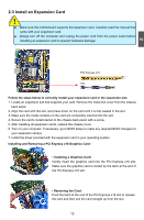
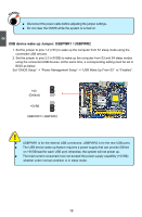
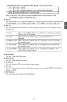
2 CAUTION WARNING! ■ Disconnect the power cable before adjusting the jumper settings. ■ Do not clear the CMOS while the system is turned on. USB device wake-up Jumper: USBPWR1 / USBPWR2 1. Set the jumper to pins 1-2 (+5V) to wake up the computer from S1 sleep mode using the connected USB devices. 2. Set the jumper to pins 2-3 (+5VSB) to wake up the computer from S3 and S4 sleep modes using the connected USB devices. At the same time, a corresponding setting must be set in BIOS as below: Set "CMOS Setup" -> "Power Management Setup" -> "USB Wake Up From S3" to "Enabled". 1 +5V 2 (Default) 3 1 +5VSB 2 3 USBPWR1/ USBPWR2 ! ■ USBPWR1 is for the internal USB connectors, USBPWR2 is for the rear USB ports. ■ The USB device wake-up feature requires a power supply that can provide 500mA on +5VSB lead for each USB port; otherwise, the system will not power up. ■ The total current consumed must not exceed the power supply capability (+5VSB) whether under normal condition or in sleep mode. 18
-
 1
1 -
2
-
3
-
4
-
5
-
6
-
7
-
8
-
9
-
10
-
11
-
12
-
13
-
14
-
15
-
16
-
17
-
18
-
19
-
 20
20 -
 21
21 -
 22
22 -
 23
23 -
 24
24 -
 25
25 -
 26
26 -
 27
27 -
 28
28 -
 29
29 -
 30
30 -
31
-
32
-
33
-
34
-
35
-
36
-
37
-
38
-
39
-
40
-
41
-
42
-
43
-
44
-
45
-
46
-
47
-
48
-
49
-
50
-
51
-
52
-
53
-
54
-
55
-
56
-
57
-
58
-
59
-
60
-
61
-
62
-
63
-
64
-
65
-
66
-
67
-
68
-
69
-
70
-
71
-
72
-
73
-
74
-
75
-
76
-
77
 |
 |