Frigidaire FCFE2425AW Installation Instructions
Frigidaire FCFE2425AW Manual
 |
View all Frigidaire FCFE2425AW manuals
Add to My Manuals
Save this manual to your list of manuals |
Frigidaire FCFE2425AW manual content summary:
- Frigidaire FCFE2425AW | Installation Instructions - Page 1
24" ELECTRIC RANGE INSTALLATION INSTRUCTIONS INSTALLATION AND SERVICE MUST BE PERFORMED BY A QUALIFIED INSTALLER. IMPORTANT: SAVE FOR LOCAL ELECTRICAL INSPECTOR'S USE. READ AND SAVE THESE INSTRUCTIONS FOR FUTURE REFERENCE. Clearances and Dimensions 1. Provide adequate clearances between the range - Frigidaire FCFE2425AW | Installation Instructions - Page 2
death. If the information in this manual is not followed exactly, a instructions with the consumer. Important Notes to the Consumer: Keep these instructions with your owner's guide Guide, read it carefully. • Be sure your range is installed and grounded properly by a qualified installer or service - Frigidaire FCFE2425AW | Installation Instructions - Page 3
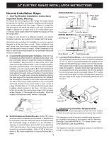
the range itself. If range is ever moved to a different location, the anti-tip brackets must also be moved and installed with the range. Instructions are provided for installation in wood or cement fastened to either the floor or wall. When installed to the wall, make sure that screws completely - Frigidaire FCFE2425AW | Installation Instructions - Page 4
is required, punch out the knockout. Risk of fire or electrical shock exists if an incorrect size range cord kit is used, the Installation Instructions are not followed, or the strain relief bracket is discarded. For mobile homes, new installation or recreational vehicles, use only a power cord kit - Frigidaire FCFE2425AW | Installation Instructions - Page 5
24" ELECTRIC RANGE INSTALLATION INSTRUCTIONS Three Conductor Wire Connection to Range If local codes permit connection of the frame grounding conductor to the neutral wire of the copper power supply - Frigidaire FCFE2425AW | Installation Instructions - Page 6
, or if connecting to 4-wire electrical system (see Figure 11): 1. Be sure that no power is supplied on the cable from residence. 2. Follow instructions on previous page for Four Conductor Wire Connection to Range (Fig. 9). 3. In the circuit breaker, fuse box or junction box (Fig. 11): a) Connect - Frigidaire FCFE2425AW | Installation Instructions - Page 7
level the range and check electrical connections. See pages 2 and 3 for proper anchoring instructions. Before You Call for Service Read the "Before You Call" and operating instruction sections in your Use & Care Manual. It may save you time and expense. The list includes common occurrences that are - Frigidaire FCFE2425AW | Installation Instructions - Page 8
INSTRUCCIONES DE INSTALACION LA ESTUFA ELECTRICA DE 24" LA INSTALACION Y EL SERVICIO DEBEN SER EFECTUADOS POR UN INSTALADOR CALIFICADO. IMPORTANTE: CONSERVE ESTAS INSTRUCCIONES PARA USO DEL INSPECTOR LOCAL DE ELECTRICIDAD. LEA Y CONSERVE ESTAS INSTRUCCIONES PARA REFERENCIA FUTURA. Espacios y - Frigidaire FCFE2425AW | Installation Instructions - Page 9
puerta del horno o en el cajón puede provocar lesiones graves y también dañar el aparato. • Si no se sigue exactamente la información de este manual, se puede producir un incendio o una descarga eléctrica que cause daños a la propiedad, lesiones personales o la muerte. Si no se sigue estrictamente - Frigidaire FCFE2425AW | Installation Instructions - Page 10
INSTRUCCIONES DE INSTALACION LA ESTUFA ELECTRICA DE 24" Pasos normales de instalación 1. Instrucción para la instalación del braquete anti-basculante Nota importante de seguridad! Para reducir el riesgo de inclinación de la cocina, ésta debe ser asegurada hacia el piso con las fijaciones de anti- - Frigidaire FCFE2425AW | Installation Instructions - Page 11
INSTRUCCIONES DE INSTALACION LA ESTUFA ELECTRICA DE 24" Cuando instale un cableado permanente, no deje el exceso de cable en el compartimento de rango. El exceso de cable en el compartimiento de rango puede no permitir que la cubierta de acceso posterior sea reemplazada adecuadamente y podría crear - Frigidaire FCFE2425AW | Installation Instructions - Page 12
INSTRUCCIONES DE INSTALACION LA ESTUFA ELECTRICA DE 24" Conexión del cable de tres conductores a la estufa Si el código local permite la conexión a tierra del conductor del marco al cable neutro del cable de alimentación eléctrica de cobre (consulte la Figura 8): 1. Retire los tornillos de la placa - Frigidaire FCFE2425AW | Installation Instructions - Page 13
INSTRUCCIONES DE INSTALACION LA ESTUFA ELECTRICA DE 24" Conexión eléctrica directa al disyuntor, la caja de fusibles o la caja de empalme Si el electrodoméstico está conectado directamente al disyuntor, la caja de fusibles o la caja de empalmes, use un cable blindado flexible o de cobre forrado, no - Frigidaire FCFE2425AW | Installation Instructions - Page 14
para obtener instrucciones de anclaje adecuadas. Antes de llamar al servicio Lea las secciones "Antes de llamar" y la instrucción de operación en su Manual de uso y cuidado. Puede ahorrarle tiempo y dinero. La lista incluye las ocurrencias comunes que no son el resultado de mano de obra o materiales
-
 1
1 -
 2
2 -
 3
3 -
 4
4 -
 5
5 -
 6
6 -
 7
7 -
8
-
9
-
10
-
11
-
12
-
13
-
14
 |
 |
1
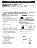
24" ELECTRIC RANGE INSTALLATION INSTRUCTIONS
INSTALLATION AND SERVICE MUST BE PERFORMED BY A QUALIFIED INSTALLER.
IMPORTANT: SAVE FOR LOCAL ELECTRICAL INSPECTOR'S USE.
READ AND SAVE THESE INSTRUCTIONS FOR FUTURE REFERENCE.
P/N
809019202 REV A (2018/11)
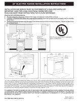
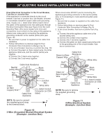
Clearances and Dimensions
1.
Provide adequate clearances between the range and adjacent combustible surfaces.
2.
Location—Check location where the range will be installed. Check for proper electrical supply, and the stability
of the floor.
3.
Dimensions that are shown must be used. Given dimensions provide minimum clearance. Contact surface must
be solid and level.
*30" (762 mm) MINIMUM CLEARANCE BETWEEN THE TOP OF THE COOKING SURFACE AND THE
BOTTOM OF AN UNPROTECTED
WOOD OR METAL CABINET; OR 24" (610 mm) MINIMUM WHEN BOTTOM OF WOOD OR METAL CABINET IS PROTECTED BY NOT
LESS THAN 1/4" (6 mm) FLAME RETARDANT MILLBOARD COVERED WITH NOT LESS THAN NO. 28 MSG SHEET STEEL, 0.015"
(0.4 mm) STAINLESS STEEL, 0.024" (0.6 mm) ALUMINUM OR 0.020" (0.5 mm) COPPER. 0" (0 mm) CLEARANCE IS THE MINIMUM FOR
THE REAR OF THE RANGE. FOLLOW ALL DIMENSION REQUIREMENTS PROVIDED ABOVE TO PREVENT PROPERTY DAMAGE,
POTENTIAL FIRE HAZARD, AND INCORRECT COUNTERTOP AND CABINET CUTS.
TO ELIMINATE THE RISK OF BURNS OR FIRE BY REACHING OVER HEATED SURFACE UNITS, CABINET STORAGE SPACE
LOCATED ABOVE THE SURFACE UNITS SHOULD BE AVOIDED. IF CABINET STORAGE IS TO BE PROVIDED, THE RISK CAN
BE REDUCED BY INSTALLING A RANGE HOOD THAT PROJECTS HORIZONTALLY A MINIMUM OF 5" (127 mm) BEYOND THE
BOTTOM OF THE CABINETS.
English - Pages 1-7
Español - Páginas 5-8
35”
89 cm
23.5”
60 cm
35”
89 cm
23-5/8”
60 cm
41.5”
105 cm
Maximum
door open
All dimensions for electrical outlet location
are maximum.
Shaded area
shows where the electrical outlet must be
installed
for flush to the wall installation.
Wall
Edge
3-3/4” (9.5 cm)
10”
(25 cm)
24”
(61 cm)
FRONT
VIEW
Minimum to wall
on either side of
range above
36’’ (914 mm)
height.
SIDE
VIEW
1”
(2.5 cm)
36”
(92 cm)
24”
(61 cm)
18”
(46 cm)
Minimum to
cabinets on
either side of
range.
13”
33 cm
Maximum depth
for cabinets
above range top.
0” (0 mm) clearance below cooking top and at rear of range.
24”
(61 cm)
25”
64 cm
30”
(76 cm)
Minimum
Refer to your serial plate for applicable
agency certifications