Frigidaire FPEC3677RF Installation Instructions (All Languages) - Page 2
Overhead Cabinet Should Not Exceed
 |
View all Frigidaire FPEC3677RF manuals
Add to My Manuals
Save this manual to your list of manuals |
Page 2 highlights
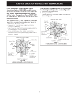
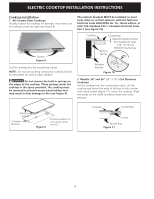
ELECTRIC COOKTOP INSTALLATION INSTRUCTIONS Overhead Cabinet Should Not Exceed a Maximum Depth of 13" (33 cm) 30" (76.2 cm) Min. Clearance Between the Top of the Cooking Platform and the Bottom of an Unprotected Wood or Metal Cabinet 24" (61 cm) Min. when Bottom of Wood or Metal Cabinet is Protected by Not Less Than 1/8" Flame Retardant Millboard Covered With Not Less Than No. 28 MGS Sheet Steel, 0.015" (0.4 mm) Stainless Steel, 0.024" (0.6 mm) Aluminum or 0.020" (0.5 mm) Copper 2 1/2" (6.4 cm) Min. From Edge of Cutout to Front Edge of Countertop A Min. J Min. Recommended Distance Between Rear Edge of Cutout and Nearest Combustible Surface Above Countertop 10" ( 25.4 cm) 18" (45.7 cm) D F E 25" Min. (63.5 cm Min.) H Min. From Edge of Cooktop to Nearest Combustible Wall (Either Side of Unit). Approximate Location of Junction Box * Letters on this figure refer to chart on front page except for G, H and J. CAUTION To eliminate the risk of burns or fire by reaching over heated surfaces, cabinet storage space located above the cooktop should be avoided. If cabinet storage is provided, risk can be reduced by installing a range hood that projects horizontally a minimum of 5" (12.7 cm) beyond the bottom of the cabinets. 12" (30.5 cm) For a drawer installation below the cooktop, allow Dimension G of clearance underneath the countertop. The drawer must not interfere with the electrical installation of the cooktop or contain flammable materials. MODEL 26" Coil Elements 30" Ceramic-Glass 30" Coil Elements 32" Ceramic-Glass 32" Coil Elements 36" Ceramic-Glass 36" Coil Elements (36" X 18") G 3½" (8.9 cm) 4" (10.2 cm) 6" (15.2 cm) 4" (10.2 cm) 6" (15.2 cm) 4" (10.2 cm) 6" (15.2 cm) 36" Coil Elements 6" (15.2 cm) (36" X 21½") H 3" (7.6 cm) 7½" (19.1 cm) 7½" (19.1 cm) 7½" (19.1 cm) 7½" (19.1 cm) 7½" (19.1 cm) 3" (7.6 cm) 7½" (19.1 cm) J 2" (5.1 cm) 2" (5.1 cm) 2¼" (5.7 cm) 2" (5.1 cm) 2¼" (5.7 cm) 2" (5.1 cm) 3" (7.6 cm) 2¼" (5.7 cm) Figure 2 - COUNTERTOP CUTOUT OPENING Important Notes to the Installer 1. Read all instructions contained in these installation instructions before installing the cooktop. 2. Remove all packing material before connecting the electrical supply to the cooktop. 3. Observe all governing codes and ordinances. 4. Be sure to leave these instructions with the consumer. Important Note to the Consumer Keep these instructions with your owner's guide for future reference. 2
-
 1
1 -
 2
2 -
 3
3 -
 4
4 -
 5
5 -
 6
6 -
 7
7 -
 8
8 -
9
-
10
-
11
-
12
-
13
-
14
-
15
-
16
-
17
-
18
-
19
-
20
-
21
-
22
-
23
-
24
 |
 |
