Fujitsu MHM2200AT Manual/User Guide - Page 107
Fujitsu MHM2200AT - Mobile 20 GB Hard Drive Manual
 |
View all Fujitsu MHM2200AT manuals
Add to My Manuals
Save this manual to your list of manuals |
Page 107 highlights
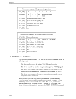
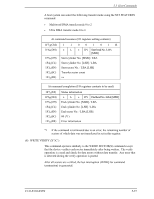
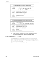
Interface At command issuance (I/O registers setting contents) 1F7H(CM) 1F6H(DH) 1F5H(CH) 1F4H(CL) 1F3H(SN) 1F2H(SC) 1F1H(FR) 0111xxxx x L x DV Head No. /LBA [MSB] Cylinder No. [MSB] / LBA Cylinder No. [LSB] / LBA Sector No. / LBA [LSB] xx xx At command completion (I/O registers contents to be read) 1F7H(ST) 1F6H(DH) 1F5H(CH) 1F4H(CL) 1F3H(SN) 1F2H(SC) 1F1H(ER) Status information x L x DV Head No. /LBA [MSB] Cylinder No. [MSB] / LBA Cylinder No. [LSB] / LBA Sector No. / LBA [LSB] xx Error information (11) INITIALIZE DEVICE PARAMETERS (X'91') The host system can set the number of sectors per track and the maximum head number (maximum head number is "number of heads minus 1") per cylinder with this command. Upon receipt of this command, the device sets the BSY bit of Status register and saves the parameters. Then the device clears the BSY bit and generates an interrupt. When the SC register is specified to X'00', an ABORTED COMMAND error is posted. Other than X'00' is specified, this command terminates normally. The parameters set by this command are retained even after reset or power save operation regardless of the setting of disabling the reverting to default setting. In LBA mode The device ignores the L bit specification and operates with the CHS mode specification. An accessible area of this command within head moving in the LBA mode is always within a default area. It is recommended that the host system refers the addressable user sectors (total number of sectors) in word 60 to 61 of the parameter information by the IDENTIFY DEVICE command. 5-30 C141-E104-03EN
-
 1
1 -
2
-
3
-
4
-
5
-
6
-
7
-
8
-
9
-
10
-
11
-
12
-
13
-
14
-
15
-
16
-
17
-
18
-
19
-
20
-
21
-
22
-
23
-
24
-
25
-
26
-
27
-
28
-
29
-
30
-
31
-
32
-
33
-
34
-
35
-
36
-
37
-
38
-
39
-
40
-
41
-
42
-
43
-
44
-
45
-
46
-
47
-
48
-
49
-
50
-
51
-
52
-
53
-
54
-
55
-
56
-
57
-
58
-
59
-
60
-
61
-
62
-
63
-
64
-
65
-
66
-
67
-
68
-
69
-
70
-
71
-
72
-
73
-
74
-
75
-
76
-
77
-
78
-
79
-
80
-
81
-
82
-
83
-
84
-
85
-
86
-
87
-
88
-
89
-
90
-
91
-
92
-
93
-
94
-
95
-
96
-
97
-
98
-
99
-
100
-
101
-
 102
102 -
 103
103 -
 104
104 -
 105
105 -
 106
106 -
 107
107 -
 108
108 -
 109
109 -
 110
110 -
 111
111 -
 112
112 -
113
-
114
-
115
-
116
-
117
-
118
-
119
-
120
-
121
-
122
-
123
-
124
-
125
-
126
-
127
-
128
-
129
-
130
-
131
-
132
-
133
-
134
-
135
-
136
-
137
-
138
-
139
-
140
-
141
-
142
-
143
-
144
-
145
-
146
-
147
-
148
-
149
-
150
-
151
-
152
-
153
-
154
-
155
-
156
-
157
-
158
-
159
-
160
-
161
-
162
-
163
-
164
-
165
-
166
-
167
-
168
-
169
-
170
-
171
-
172
-
173
-
174
-
175
-
176
-
177
-
178
-
179
-
180
-
181
-
182
-
183
-
184
-
185
-
186
-
187
-
188
-
189
-
190
-
191
-
192
-
193
-
194
-
195
-
196
-
197
-
198
-
199
-
200
-
201
-
202
-
203
-
204
-
205
-
206
-
207
-
208
-
209
-
210
-
211
-
212
-
213
-
214
-
215
-
216
-
217
-
218
-
219
-
220
-
221
-
222
-
223
-
224
-
225
-
226
-
227
-
228
-
229
-
230
-
231
-
232
 |
 |
