Garmin Compact Reactor 40 Hydraulic Autopilot with GHC 20 Corepack Installatio - Page 4
Hydraulic Layouts
 |
View all Garmin Compact Reactor 40 Hydraulic Autopilot with GHC 20 Corepack manuals
Add to My Manuals
Save this manual to your list of manuals |
Page 4 highlights
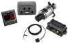
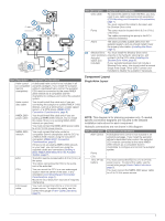
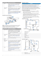
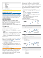
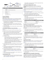
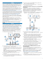
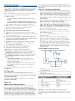
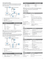
Item Description CCU Ä NMEA 2000 Å network Important Considerations You can mount the CCU in a non-submerged location near the center of the boat, in any orientation (CCU Mounting and Connection Considerations, page 1). Mount the CCU away from sources of magnetic interference. You must connect the helm control or compatible Garmin chartplotter and the CCU to a NMEA 2000 network using the included T-connectors (NMEA 2000® Connection Considerations, page 2). If there is not an existing NMEA 2000 network on your boat, you can build one using the supplied cables and connectors (Building a Basic NMEA 2000 Network for the Autopilot System, page 7). Dual-Helm Layout Guidelines Hydraulic Layouts NOTICE If the steering system in your boat does not match any of the hydraulic layouts in this manual and you are unsure how to install the pump, contact Garmin Product Support. Before you start the pump installation, identify the type of hydraulic steering system in your boat. Each boat is different, and you must consider certain aspects of the existing hydraulic layout before deciding where to mount the pump. Important Considerations • The three hydraulic ports on the pump are 1/4 in. NPT. • Garmin recommends using T-connectors to connect the hydraulic lines to the pump. • To allow for easy pump disabling and removal, Garmin recommends installing shut-off valves in the hydraulic lines between the pump manifold and T-connectors. • Teflon® tape must not be used on any hydraulic fitting. • An appropriate thread sealant should be used on all pipe threads in the hydraulic system. Single-Helm Layout NOTE: This diagram is for planning purposes only. If needed, specific connection diagrams are included in the detailed installation instructions for each component. Hydraulic connections are not shown in this diagram. Item Description Helm control À 12 to 24 Vdc Á battery Pump  ECU à NMEA 2000 Ä network CCU Å Important Considerations A dedicated helm control is not included in all autopilot packages. If you install the autopilot without a dedicated helm control, the autopilot CCU must be connected to the same NMEA 2000 network as a compatible Garmin chartplotter to configure and control the autopilot system. You must connect the ECU to a 12 to 24 Vdc power source. To extend this cable, use the correct wire gauge (Power Cable Extensions, page 5). You must connect the NMEA 2000 power cable to a 9 to 16 Vdc power source. You must connect the helm control or compatible Garmin chartplotter and the CCU to a NMEA 2000 network using the included T-connectors (NMEA 2000® Connection Considerations, page 2). If there is not an existing NMEA 2000 network on your boat, you can build one using the supplied cables and connectors (Building a Basic NMEA 2000 Network for the Autopilot System, page 7). You can mount the CCU in a non-submerged location near the center of the boat, in any orientation (CCU Mounting and Connection Considerations, page 1). Mount the CCU away from sources of magnetic interference. Shadow Drive valve À Starboard line Á Return line  Pump à Port line Ä Shut-off valves Å Helm Æ Steering cylinder Ç Dual-Helm Layout Return line À Shadow Drive valve Á 4
-
 1
1 -
 2
2 -
 3
3 -
 4
4 -
 5
5 -
 6
6 -
 7
7 -
 8
8 -
 9
9 -
 10
10 -
11
-
12
 |
 |
