Garmin ECHOMAP Plus 44cv Installation Instructions - Page 3
Connecting to a Garmin Device to Share User Data, Connecting the Device to a Transducer, Connecting
 |
View all Garmin ECHOMAP Plus 44cv manuals
Add to My Manuals
Save this manual to your list of manuals |
Page 3 highlights
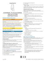
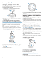
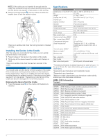
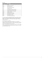
2 If necessary, extend the wires using 0.82 mm2 (18 AWG) or larger wire. 3 Connect the red wire to the positive terminal on the battery or fuse block, and connect the black wire to the negative terminal. Wiring Harness • The wiring harness is used for NMEA® 0183 devices, and to share route and waypoint information. • The wiring harness connects the device to power and NMEA 0183 devices. • The device has one internal NMEA 0183 port that is used to connect to NMEA 0183 compliant devices. • If it is necessary to extend the power and ground wires, you must use 0.82 mm2 (18 AWG) or larger wire. • If it is necessary to extend the NMEA 0183 or alarm wires, you must use .33 mm2 (22 AWG) wire. Item Wire Function NMEA 0183 internal port Rx (in) NMEA 0183 internal port Tx (out) Ground (power and NMEA 0183) Power Wire Color Brown Blue Black Red NMEA 0183 Connection Considerations • The installation instructions provided with your NMEA 0183 compatible device should contain the information you need to identify the transmitting (Tx) and receiving (Rx) A (+) and B (-) wires. Each port may have one or two transmitting wires, or one or two receiving wires. • When connecting NMEA 0183 devices to ports containing two transmitting (Tx) wires or two receiving (Rx) wires each, it is not necessary for the NMEA 0183 device to connect to a common ground. • When connecting a NMEA 0183 device to ports containing one transmitting (Tx) wire or one receiving (Rx) wire each, the NMEA 0183 device must be connected to a common ground. • When the device is mounted in a location that prevents the internal antenna from acquiring a satellite signal, you can connect an external GPS 19x antenna through a NMEA 0183 connection. For more information, see the GPS 19x Installation Instructions. NMEA 0183 Connection Diagram + - Item Garmin Wire Function Power Ground Tx/Rx Tx Rx Garmin Wire Color Red Black Blue Brown NMEA 0183 Device Wire Function Power Data ground Tx/Rx/B (-) Rx/A (+) Tx/A (+) Connecting to a Garmin Device to Share User Data You can connect the ECHOMAP Plus device to a compatible Garmin device to share user data, such as waypoints. If the devices are mounted near each other, you can connect the blue and brown wires. If the devices are mounted too far apart for the wires to reach, you can connect the devices using a User Data Sharing Cable (010-12234-06). 1 Make sure both devices are connected to the same ground. 2 Complete an action: • If the devices are mounted near each other, connect the blue wire from the first device to the brown wire of the second, and connect the brown wire from the first device to the blue wire of the second. • If the devices are not mounted near each other, obtain a User Data Sharing Cable (010-12234-06), and connect the devices following the instructions included with the cable. 3 On both devices, select Navigation Info > Manage Data > User Data Sharing. User data is shared between the connected devices. If you select Clear User Data, data is removed from both connected devices. Connecting the Device to a Transducer Go to www.garmin.com/transducers or contact your local Garmin dealer to determine the appropriate type of transducer for your needs. 1 Follow the instructions provided with your transducer to correctly install it on your boat. 2 Route the transducer cable to the back of your device, away from sources of electrical interference. 3 Connect the transducer cable to the appropriate port on the cradle. Connecting the Cables to the Cradle The connectors on the cables are keyed to fit in only in the correct ports on the cradle. The connected cables are held in place by a locking bracket. 1 Slide the cable locking bracket up from the bottom and remove the bracket from the cradle. 2 Compare the divots on each cable connector to the keying on each port to determine which cable corresponds to each port. Item Description 12 Vdc power source Wiring harness NMEA 0183 compliant device 3 Fully and firmly insert each cable through a hole in the cradle, and securely connect each cable to a port. 3
-
 1
1 -
 2
2 -
 3
3 -
 4
4 -
 5
5 -
 6
6
 |
 |
