Garmin GHP Reactor Hydraulic Autopilot Installation Instructions
Garmin GHP Reactor Hydraulic Autopilot Manual
 |
View all Garmin GHP Reactor Hydraulic Autopilot manuals
Add to My Manuals
Save this manual to your list of manuals |
Garmin GHP Reactor Hydraulic Autopilot manual content summary:
- Garmin GHP Reactor Hydraulic Autopilot | Installation Instructions - Page 1
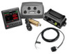
GHP™ Reactor Hydraulic Installation Instructions Important Safety Information WARNING See the Important Safety and Product Information guide in the product box for product warnings and other important information. You are responsible for the safe and prudent operation of your vessel. The autopilot - Garmin GHP Reactor Hydraulic Autopilot | Installation Instructions - Page 2
of the GHP Reactor Hydraulic autopilot system. For the ECU, extension cables are available from your local Garmin dealer or at www.garmin.com. ◦ This cable must not be cut. Finding hydraulic steering lines of your boat. It detects when you manually take control of the helm and suspends autopilot - Garmin GHP Reactor Hydraulic Autopilot | Installation Instructions - Page 3
a Basic NMEA 2000 Network for the Autopilot System). Dual-Helm Layout Guidelines NOTE: This diagram is for planning purposes only. If needed, specific connection diagrams are included in the detailed installation instructions for each component. Hydraulic connections are not shown in this diagram - Garmin GHP Reactor Hydraulic Autopilot | Installation Instructions - Page 4
connecting it to a NMEA 2000 network. To use advanced features of the autopilot, optional NMEA 2000compatible or NMEA 0183-compatible devices, such as a wind steel screws may bind when screwed into fiberglass and overtightened. Garmin recommends applying an anti-seize lubricant to the screws before - Garmin GHP Reactor Hydraulic Autopilot | Installation Instructions - Page 5
separately) must be installed in your hydraulic steering lines so the GHP Reactor Hydraulic autopilot can steer your boat. When you purchase a pump sold by Garmin, it will have the correct cables, connectors, and instructions. Follow the installation instructions provided with your pump to mount it - Garmin GHP Reactor Hydraulic Autopilot | Installation Instructions - Page 6
blocker should be applied to the pump after all hydraulic and electrical connections are made and the hydraulic system has been bled. Connecting the CCU 1 , select Manuals on the product page for your device at www.garmin.com. Building a Basic NMEA 2000 Network for the Autopilot System NOTICE - Garmin GHP Reactor Hydraulic Autopilot | Installation Instructions - Page 7
following the instructions provided with the device. Configuring the Autopilot The autopilot must be NOTE: If the autopilot does not perform well using None as the speed source, Garmin recommends connecting a numbers do not align, there may be a problem with the NMEA 2000 speed source or connection. - Garmin GHP Reactor Hydraulic Autopilot | Installation Instructions - Page 8
if you want to run the autotune procedure at a later time or if you want to manually adjust the gain settings (not recommended) (Adjusting the Autopilot Gain Settings). Gain: Sets how tightly the autopilot holds the heading and how aggressively it makes turns. Counter Gain: Sets how aggressively the - Garmin GHP Reactor Hydraulic Autopilot | Installation Instructions - Page 9
Dealer Autopilot Setup > Compass Setup > Set North > Begin. 3 Continue to drive the boat at cruising speed in a straight line and follow the on-screen instructions. setting if the autopilot turns too quickly. • Decrease the setting if the autopilot turns too slowly. When you manually adjust the - Garmin GHP Reactor Hydraulic Autopilot | Installation Instructions - Page 10
define north (Setting North). • Select Autopilot Tuning > Autotune to start the automatic autopilot tuning procedures (Performing the Autotune Procedure). 4 Follow the on-screen instructions. Defining Individual Configuration Settings Manually Configuring certain configuration settings may require - Garmin GHP Reactor Hydraulic Autopilot | Installation Instructions - Page 11
at 9 Vdc) *The device withstands incidental exposure to water of up to 1 m for up to 30 min. For more information, go to www.garmin.com/waterrating. Alarm Specification Dimensions (L×diameter) Weight Temperature range Cable length Measurement 29/32 × 1 in. (23 × 25 mm) 2.4 oz. (68 g) From 5°F to - Garmin GHP Reactor Hydraulic Autopilot | Installation Instructions - Page 12
Configuration Settings Although all of the configuration is typically completed automatically through wizards, you can manually adjust any setting to fine-tune the autopilot. Advanced configuration settings are available only when using Dealer Mode (Enabling Dealer Configuration). User-specific - Garmin GHP Reactor Hydraulic Autopilot | Installation Instructions - Page 13
set this value too low, the autopilot can overshoot a turn when attempting to not be correctly installed. If the problem persists, you can bypass this error safe place. Contacting Garmin Product Support • Go to www.garmin.com/support and click Contact Support for in-country support information. • In - Garmin GHP Reactor Hydraulic Autopilot | Installation Instructions - Page 14
Ltd. or its subsidiaries, registered in the USA and other countries. GHP™, GHC™, Reactor™, and Shadow Drive™ are trademarks of Garmin Ltd. or its subsidiaries. These trademarks may not be used without the express permission of Garmin. NMEA®, NMEA 2000®, and the NMEA 2000 logo are trademarks of
-
 1
1 -
 2
2 -
 3
3 -
 4
4 -
 5
5 -
 6
6 -
 7
7 -
8
-
9
-
10
-
11
-
12
-
13
-
14
 |
 |

GHP
™
Reactor
Hydraulic
Installation Instructions
Important Safety Information
WARNING
See the
Important Safety and Product Information
guide in the
product box for product warnings and other important
information.
You are responsible for the safe and prudent operation of your
vessel. The autopilot is a tool that enhances your capability to
operate your boat. It does not relieve you of the responsibility of
safely operating your boat. Avoid navigational hazards and
never leave the helm unattended.
Always be prepared to promptly regain manual control of your
boat.
Learn to operate the autopilot on calm and hazard-free open
water.
Use caution when operating the autopilot near hazards in the
water, such as docks, pilings, and other boats.
CAUTION
When in use, beware of hot motor and solenoid components
and the risk of entrapment from moving parts.
Failure to install and maintain this equipment in accordance with
these instructions could result in damage or injury.
NOTICE
To avoid damage to your boat, the autopilot system should be
installed by a qualified marine installer. Specific knowledge of
hydraulic steering componentry and marine electrical systems is
required for proper installation.
Installation Preparation
The autopilot system consists of multiple components. You
should familiarize yourself with all of the component mounting
and connection considerations before beginning installation. You
must know how the components operate together in order to
correctly plan the installation on your boat.
You can consult the layout diagrams (
Power and Data Layout
)
to help understand the mounting and connection considerations.
You should lay out all of the components on the boat as you
plan the installation to make sure your cables will reach each
component. If needed, extension cables (sold separately) for
various components are available from your Garmin
®
dealer or
from
www.garmin.com
.
You should record the serial number of each component for
registration and warranty purposes.
Tools Needed
•
Safety glasses
•
Drill and drill bits
•
Wrenches
•
90 mm (3.5 in.) hole saw or a rotary cutting tool
•
Wire cutters/strippers
•
Phillips and flat screwdrivers
•
Cable ties
•
Waterproof wire connectors (wire nuts) or heat-shrink tubing
and a heat gun
•
Marine sealant
•
Marine corrosion inhibitor spray
•
Portable or handheld compass (to test for magnetic
interference)
•
Hydraulic hose with machine-crimped or field-replaceable
fittings that have a minimum rating of 1000 lbf/in
2
•
Hydraulic T-fittings
•
Inline hydraulic shut-off valves
•
Hydraulic fluid
•
Thread sealant
•
Hydraulic bleeding equipment
•
Anti-seize lubricant (optional)
NOTE:
Mounting screws are provided for the main components
of the autopilot system. If the provided screws are not
appropriate for the mounting surface, you must provide the
correct types of screws.
Mounting and Connection Considerations
The autopilot components connect to each other and to power
using the included cables. Ensure that the correct cables reach
each component and that each component is in an acceptable
location before mounting or wiring any components.
Helm Control Mounting Considerations
NOTICE
This device should be mounted in a location that is not exposed
to extreme temperatures or conditions. The temperature range
for this device is listed in the product specifications. Extended
exposure to temperatures exceeding the specified temperature
range, in storage or operating conditions, may cause device
failure. Extreme-temperature-induced damage and related
consequences are not covered by the warranty.
The mounting surface must be flat to avoid damaging the device
when it is mounted.
Using the included hardware and template, you can flush mount
the device in the dashboard. If you want to mount the device
using an alternative method where it appears flat with the front
of the dashboard, you must purchase a flat-mount kit
(professional installation recommended) from your Garmin
dealer.
When selecting a mounting location, observe these
considerations.
•
The mounting location should be at or below eye level to
provide optimal viewing as you operate your vessel.
•
The mounting location should allow easy access to the keys
on the device.
•
The mounting surface must be strong enough to support the
weight of the device and protect it from excessive vibration or
shock.
•
To avoid interference with a magnetic compass, the device
should not be installed closer to a compass than the
compass-safe distance value listed in the product
specifications.
May 2015
Printed in Taiwan
190-01768-02_0B